Vertical Lathe Hydraulic Fixture Diagram – 3D Model SolidWorks
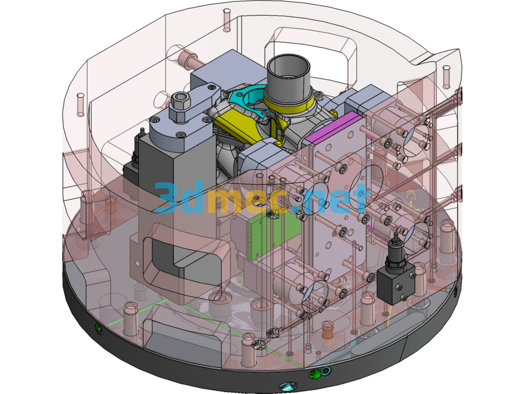
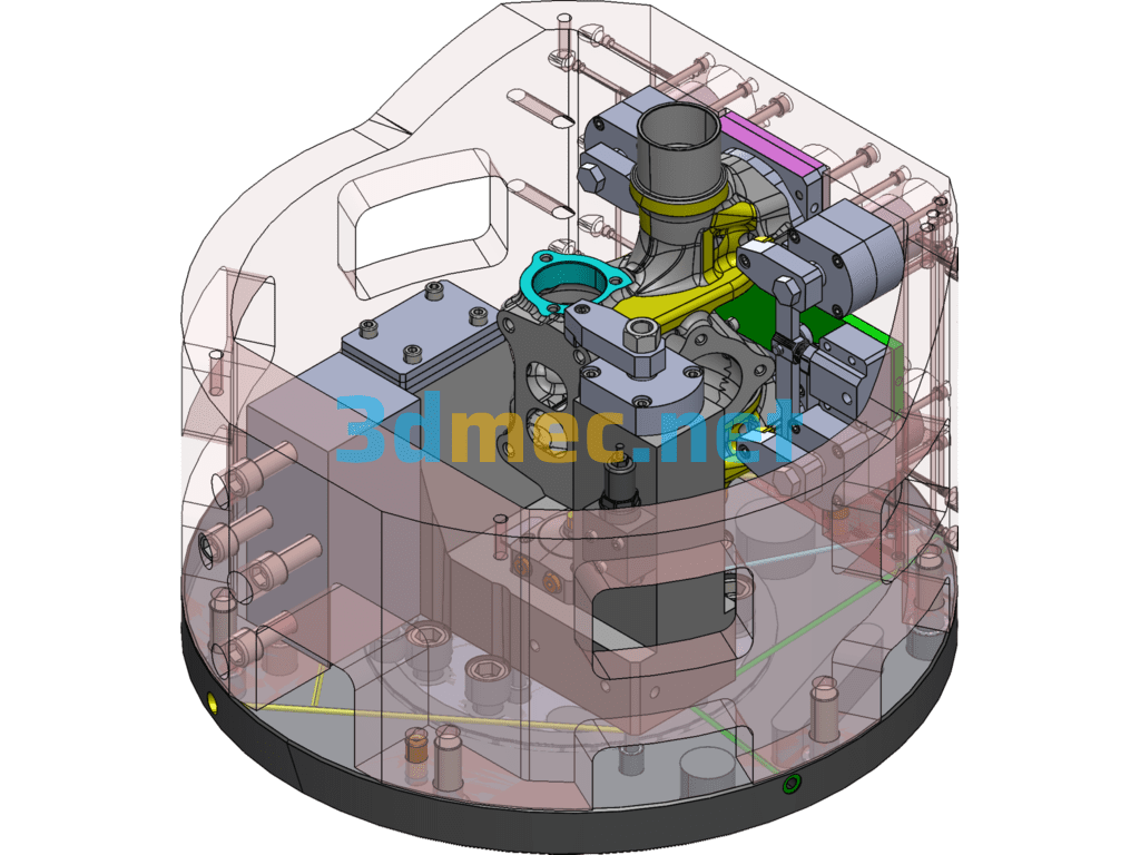
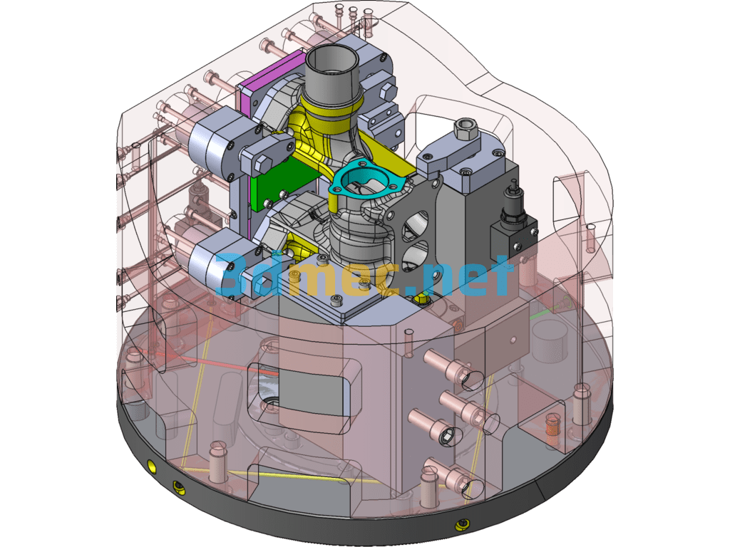
This set of clamps is a vertical lathe hydraulic clamp, and the machine tool supplies oil. The clamp is positioned by two pins on one side and clamped by the cylinder. The cylinder movement sequence is 1# push cylinder → 2# corner cylinder → 3# support cylinder → 4# corner cylinder; the total clamping weight is about 280kg.
Specification: Vertical Lathe Hydraulic Fixture Diagram – 3D Model SolidWorks
|
User Reviews
Be the first to review “Vertical Lathe Hydraulic Fixture Diagram – 3D Model SolidWorks”
You must be logged in to post a review.



There are no reviews yet.