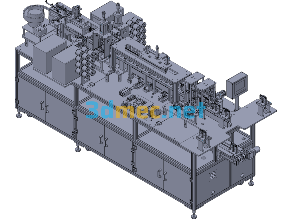
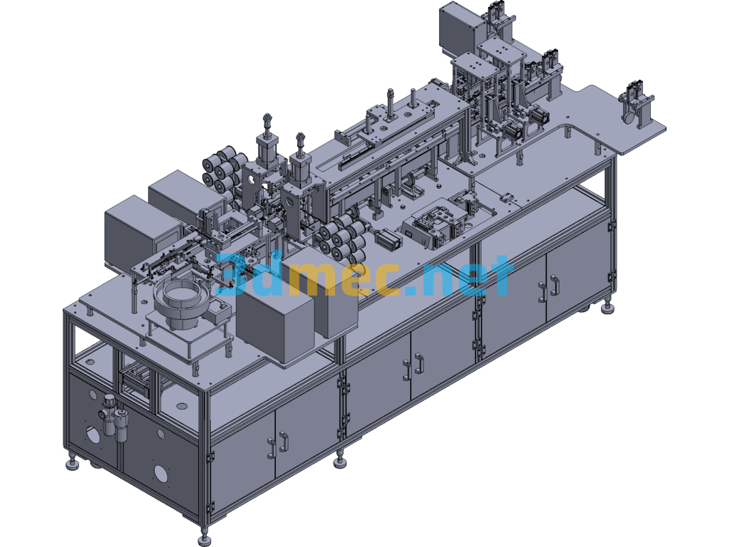
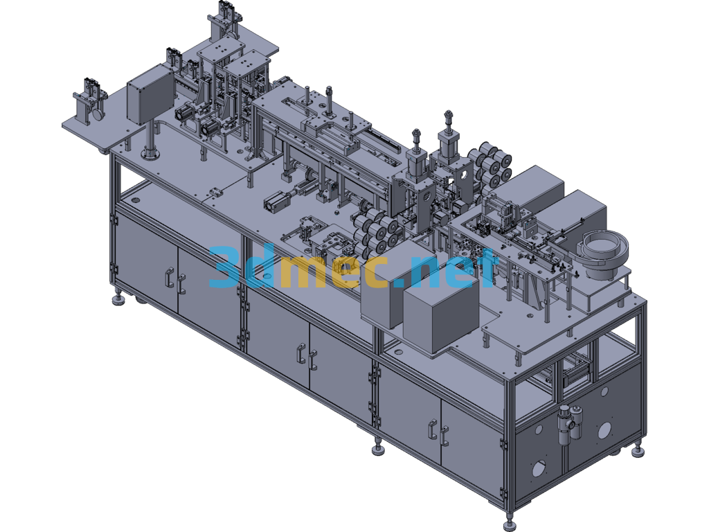
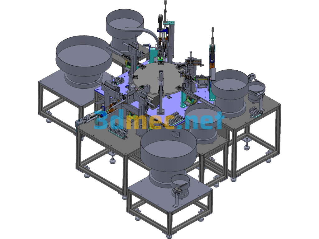
USB-3.0 Wire Processing Line – 3D Model Exported
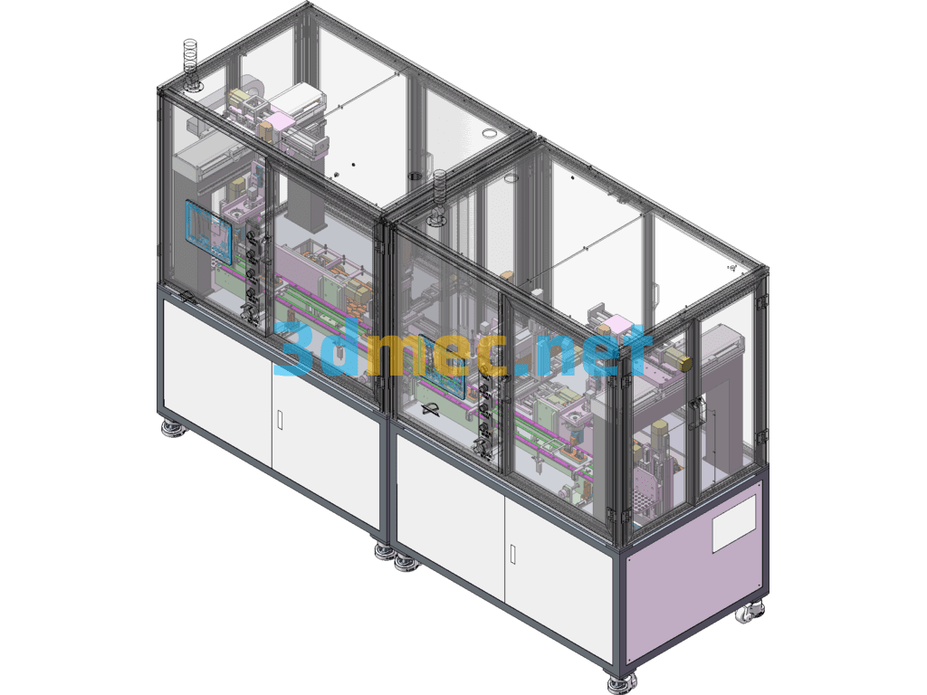
The Cable wire is pushed into the chute through the clamp positioning, and the push claw is used to transport it to the following workstations: cutting, peeling off the jacket, dipping in flux & tin, pressing tin, soldering, etc. Finally, the USB-3.0 connector is placed as required It is welded together with the Cable, and the finished product is transported to the location of the positioning table staff through the recovery mechanism, and the cycle is continued. Efficiency evaluation: It takes about 10 seconds to complete the actions (cutting core wires, peeling off outer covering, dipping flux & tin, pressing tin core wires, sorting and positioning connectors, soldering connectors, etc.) and outputs 2 lines. , the production capacity is estimated to be 720pcs/h.
USB-3.0 wire processing line staffing: (1 person) Reserve 1 person, depending on the wire positioning proficiency.
Specification: USB-3.0 Wire Processing Line – 3D Model Exported
|
User Reviews
Be the first to review “USB-3.0 Wire Processing Line – 3D Model Exported”
You must be logged in to post a review.



There are no reviews yet.