


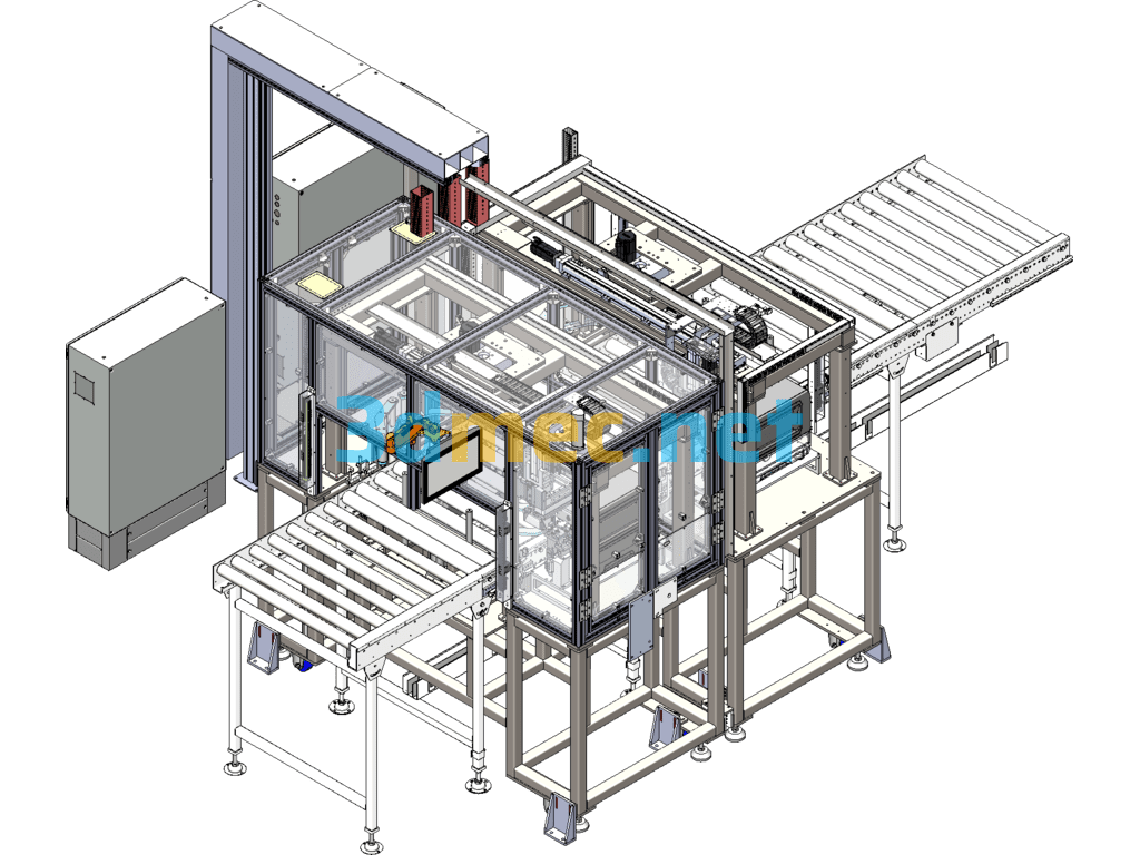
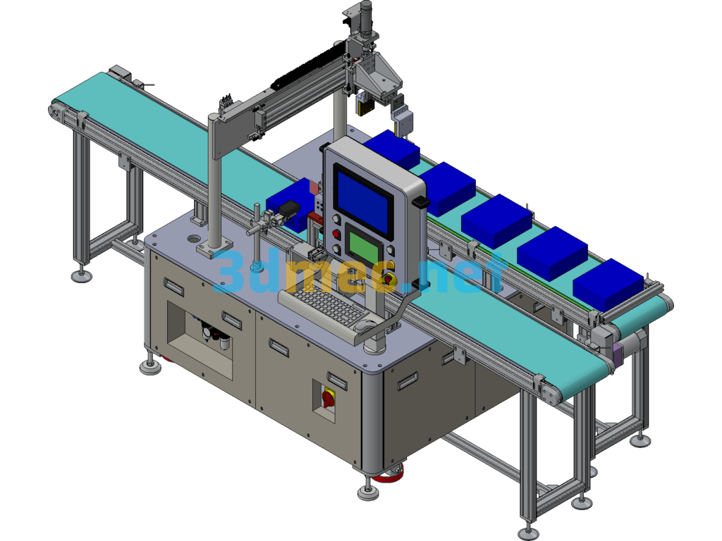
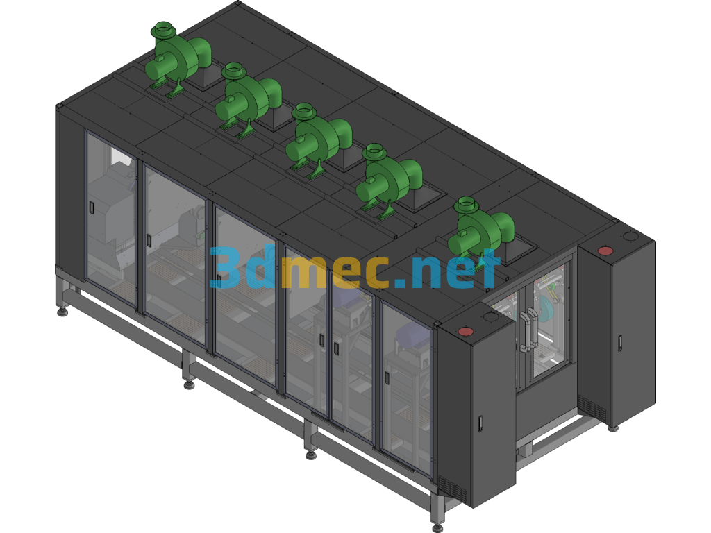
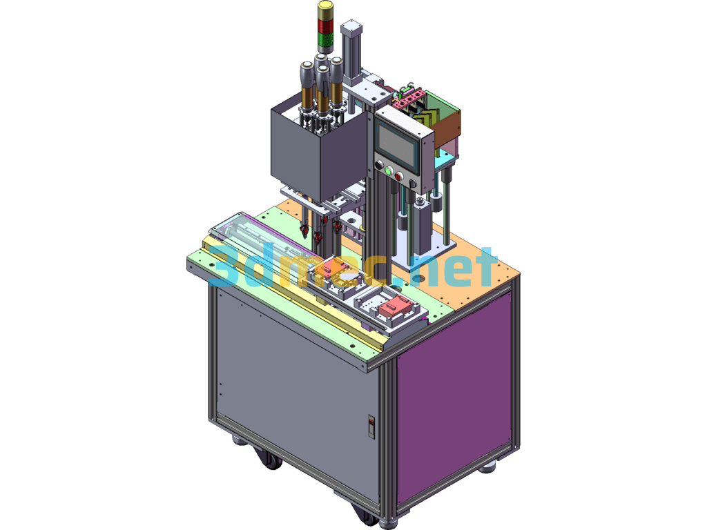
Plug-in soldering production line ….. 1.Adopting over-tin furnace mode, realizing several different styles of PCB over the furnace at the same time. n 2.Adopting up and down board walking type. n 3. After product welding, the fixture returns to the board according to the type of barcode automatically return to the corresponding position. n 4. After the plug-in is completed, there is no handling action, and the direction of plug-in is 90 degrees from the direction of the furnace. n 5. The line body is modularized, i.e. each branch line can be combined at will in the case of unrestricted space. n 6. The operation foot position has a fixture protection cover to prevent the fixture from being damaged. n 7. The plug-in material rack adopts double-layer design, and the plug-in material box has the function of recycling. n 8. Lighting adopts overall lampshade type lighting. n 9. Add air extraction ducts and integrate them into the line body, adopting splicable ducts. n 10. One of the workstations in each group of plug-in lines contains a concealable work surface, which can realize n Dual function of insertion/tinning. n 11. Each insertion station has a monitor displaying an instruction card.
Specification: Selective Welding Lines SolidWorks 3D Model
|
User Reviews
Be the first to review “Selective Welding Lines SolidWorks 3D Model”
You must be logged in to post a review.


There are no reviews yet.