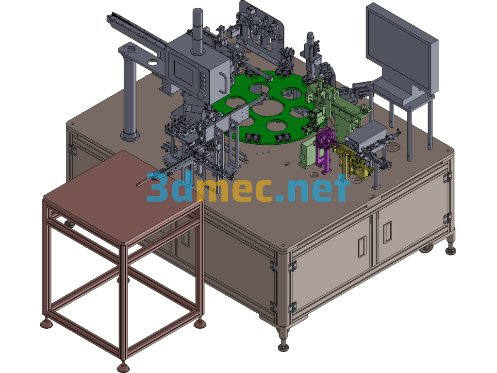
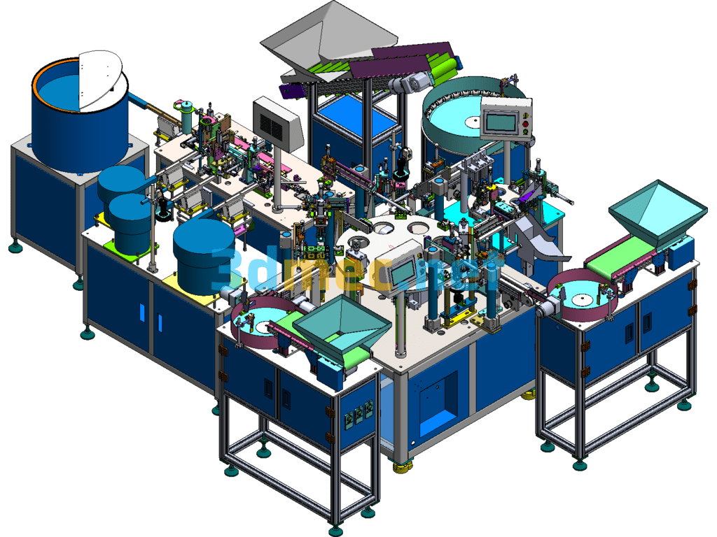
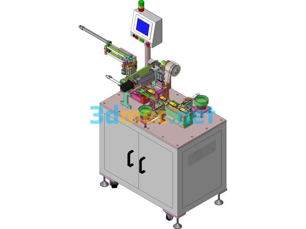
Rotary Riveting Machine Spinning Riveting Machine – 3D Model SolidWorks
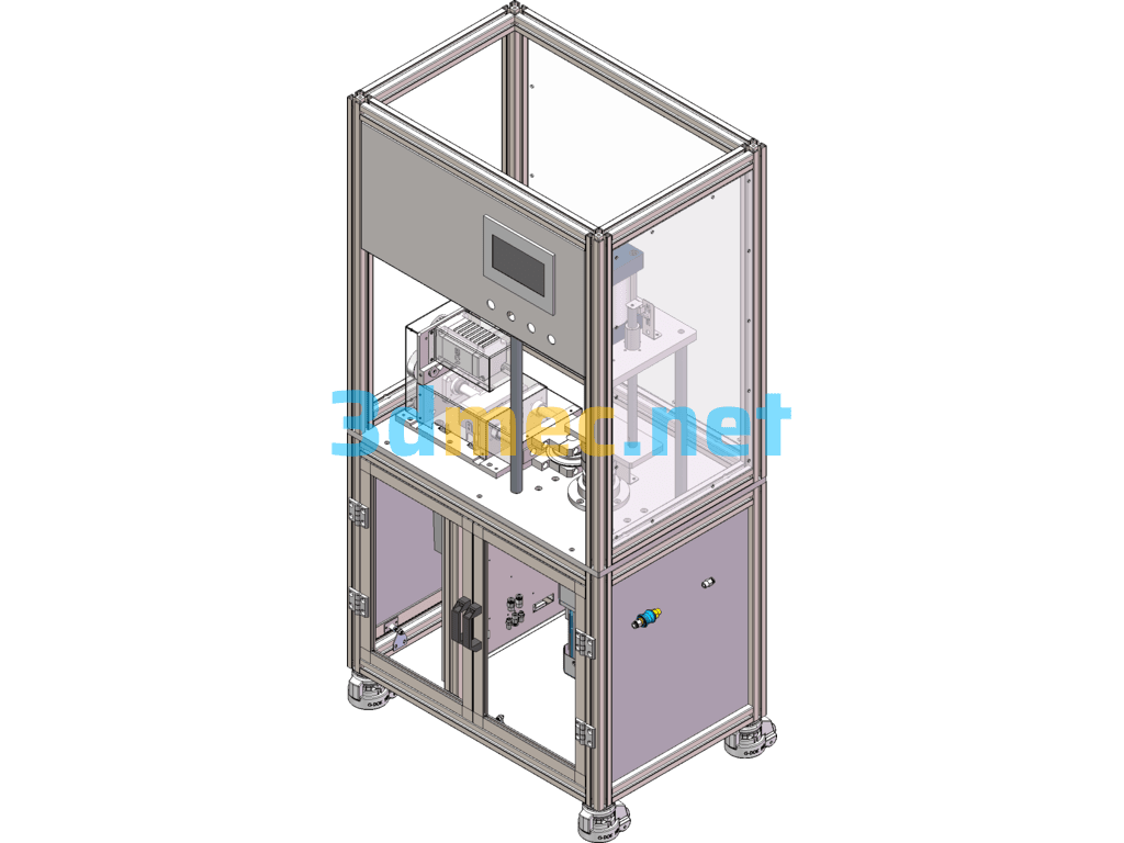
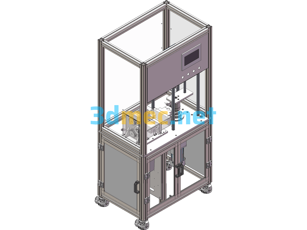
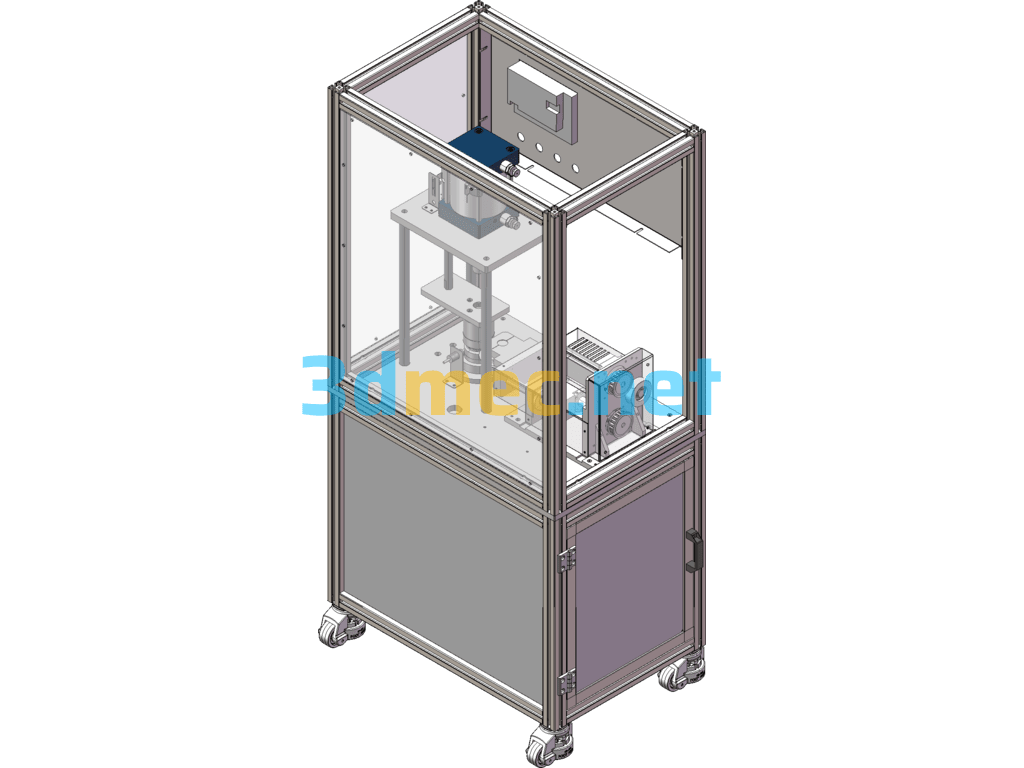
Gaskets and upper covers are loaded manually. The product body is manually placed into the equipment tooling, and the gasket is taken out and placed on the product. Then a upper cover is manually placed on top of the gasket. After pressing the start button, the pressure cylinder on the upper part of the equipment presses down. After the product is pressed into place, the main motor rotates to drive the product to rotate, and the edge banding knife quickly moves to the vicinity of the product [The specific position can be adjusted through the screen. , The edge banding knife feeds slowly for riveting (the edge banding knife rotates after contacting the product), and the edge banding position and holding time can be adjusted through the screen. After that, the product is automatically released and unloaded manually.
It contains equipment solutions, product 3D drawings, BOM tables, and assembly videos.
Specification: Rotary Riveting Machine Spinning Riveting Machine – 3D Model SolidWorks
|
User Reviews
Be the first to review “Rotary Riveting Machine Spinning Riveting Machine – 3D Model SolidWorks”
You must be logged in to post a review.





There are no reviews yet.