Resistor Automatic Cutting Test Machine Equipment (Including Detailed DFM) – 3D Model SolidWorks
 - 3D Model SolidWorks 1")
 - 3D Model SolidWorks 2")
 - 3D Model SolidWorks 3")
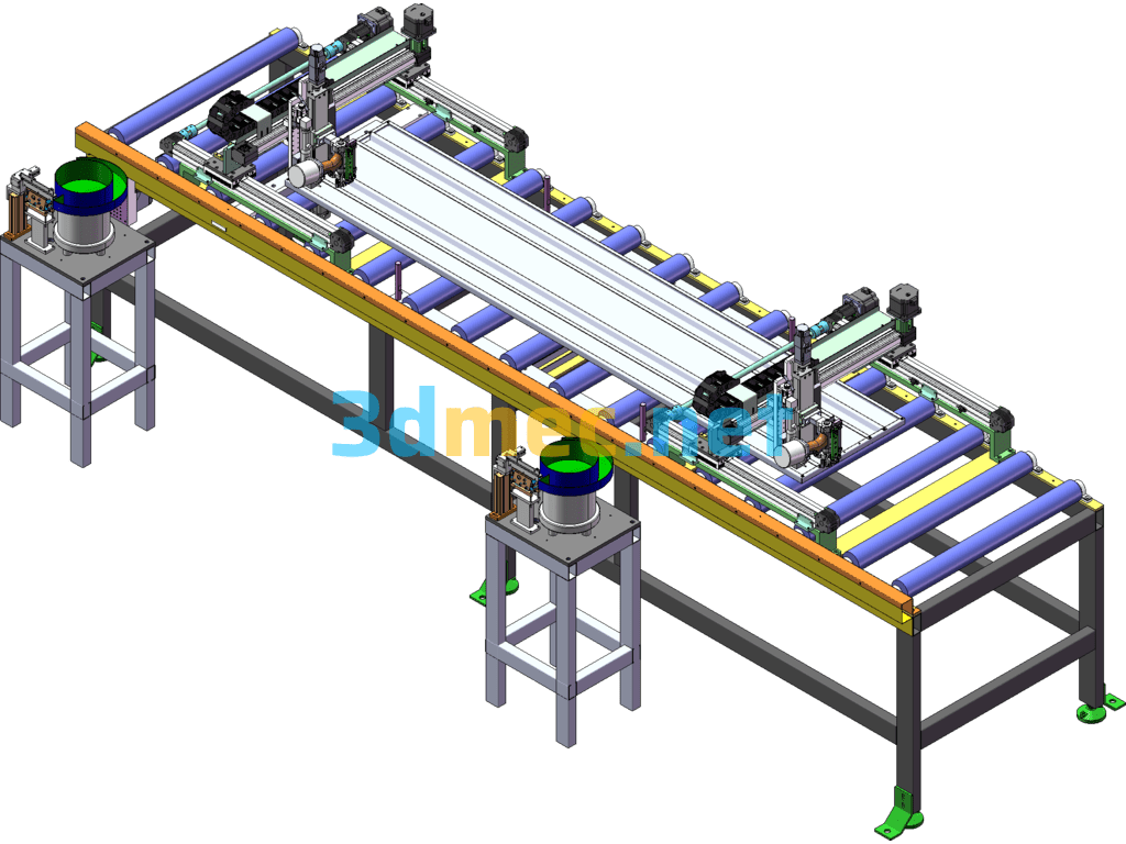
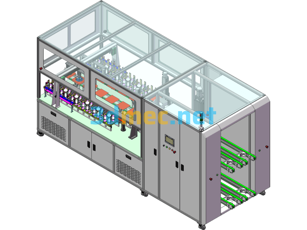
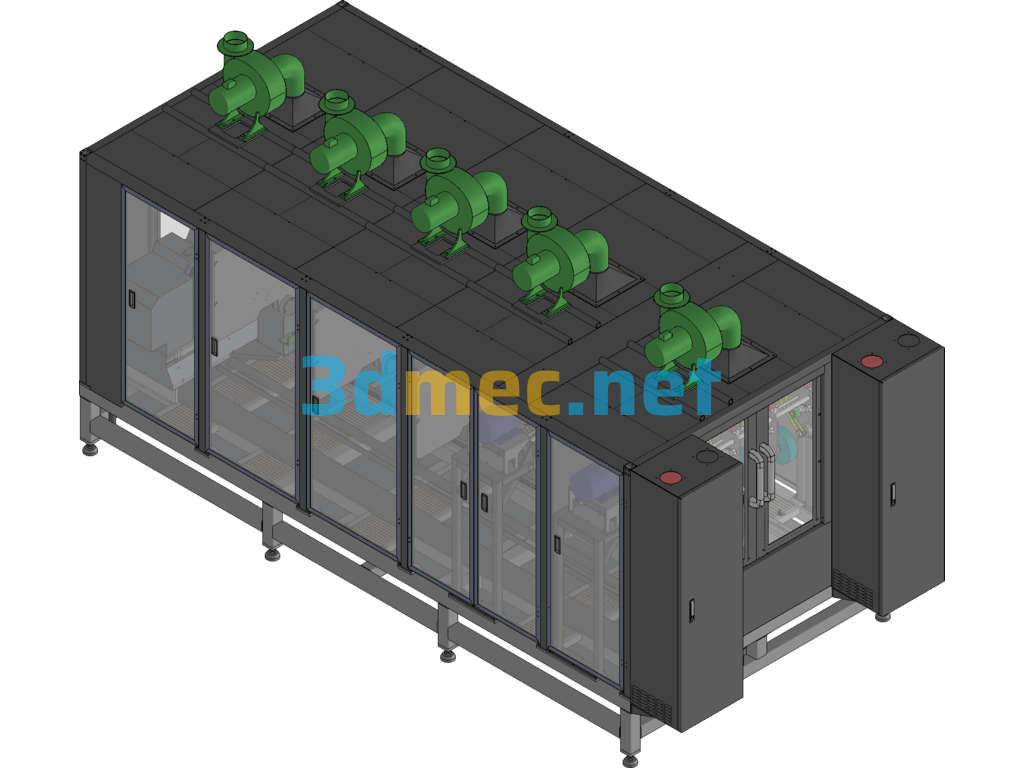
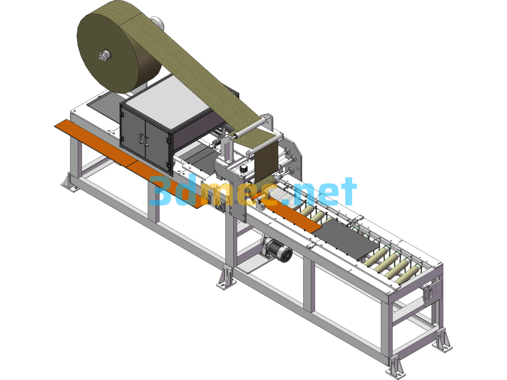
Resistance cutting test machine equipment process:
1. Manually place the product in the left and right feeding placement fixture for positioning;
2. The feeding module moves the product into the equipment;
3. The straightening module straightens the electrode antennae, and the module can be switched left and right for straightening;
4. The feeding module sends the product into the power-on test module and clamps the resistance value on the side;
5. The module moves the product to the left and right cutting for stamping and cutting;
6. Manual unloading after completion.
Specification: Resistor Automatic Cutting Test Machine Equipment (Including Detailed DFM) – 3D Model SolidWorks
|
User Reviews
Be the first to review “Resistor Automatic Cutting Test Machine Equipment (Including Detailed DFM) – 3D Model SolidWorks”
You must be logged in to post a review.

Resistor Automatic Cutting Test Machine Equipment (Including Detailed DFM) – 3D Model SolidWorks

There are no reviews yet.