Output Driving Gear Hydraulic Fixture Assembly Diagram – 3D Model SolidWorks


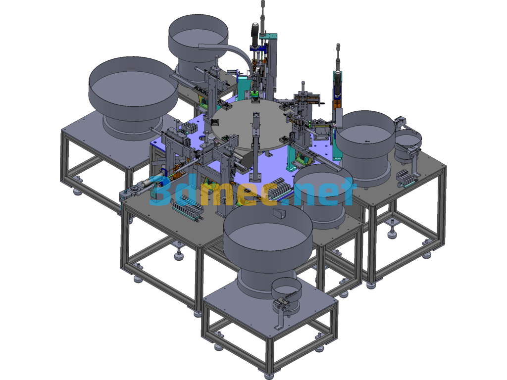
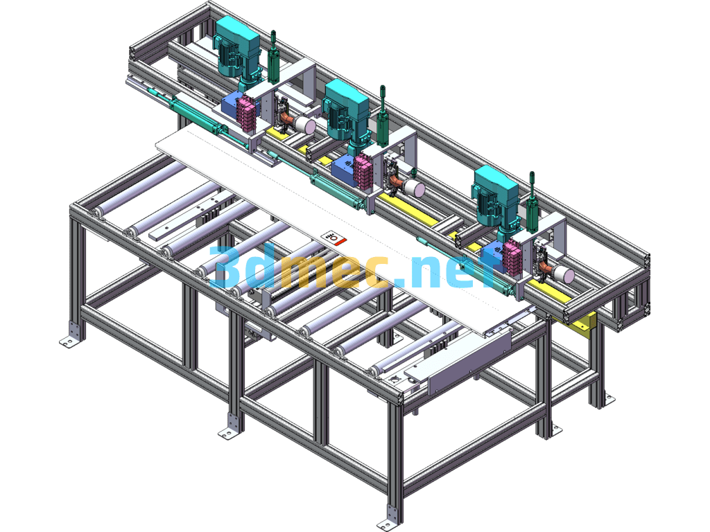
This figure is the assembly diagram of the output driving gear 416AHA-1502148 hydraulic clamp; this clamp is matched with the machine tool CMV510A, the workbench size is 600X360; OP10 processes 2X
Specification: Output Driving Gear Hydraulic Fixture Assembly Diagram – 3D Model SolidWorks
|
User Reviews
Be the first to review “Output Driving Gear Hydraulic Fixture Assembly Diagram – 3D Model SolidWorks”
You must be logged in to post a review.

Output Driving Gear Hydraulic Fixture Assembly Diagram – 3D Model SolidWorks

There are no reviews yet.