Micromotor Rotor Retaining Spring Tooling – 3D Model SolidWorks
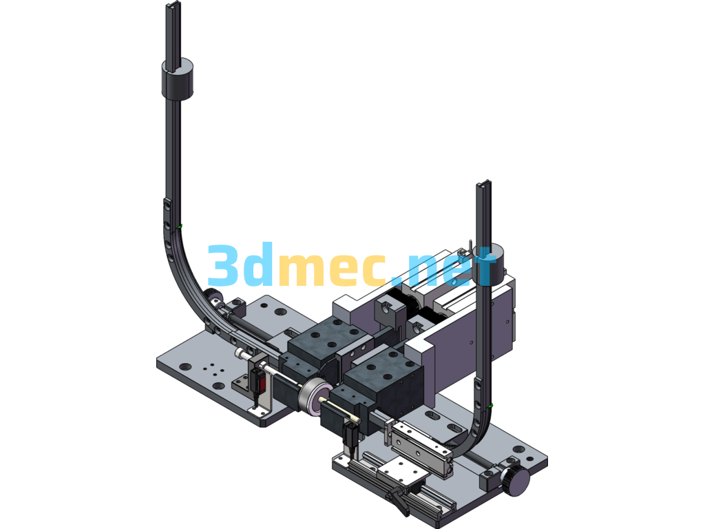
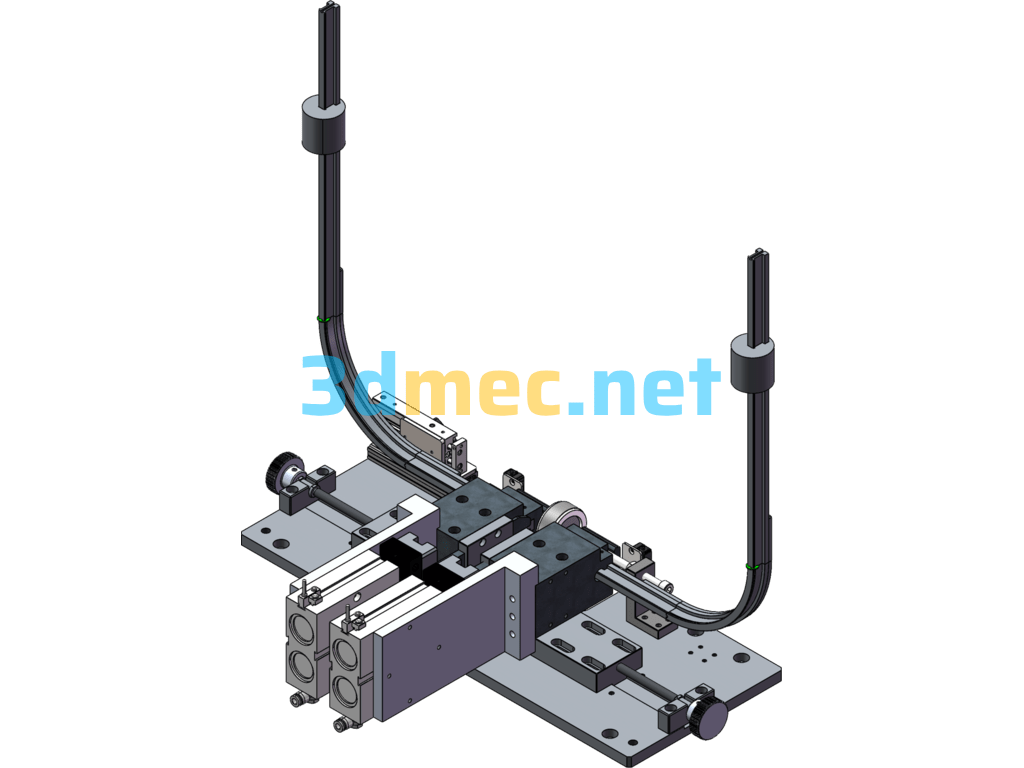
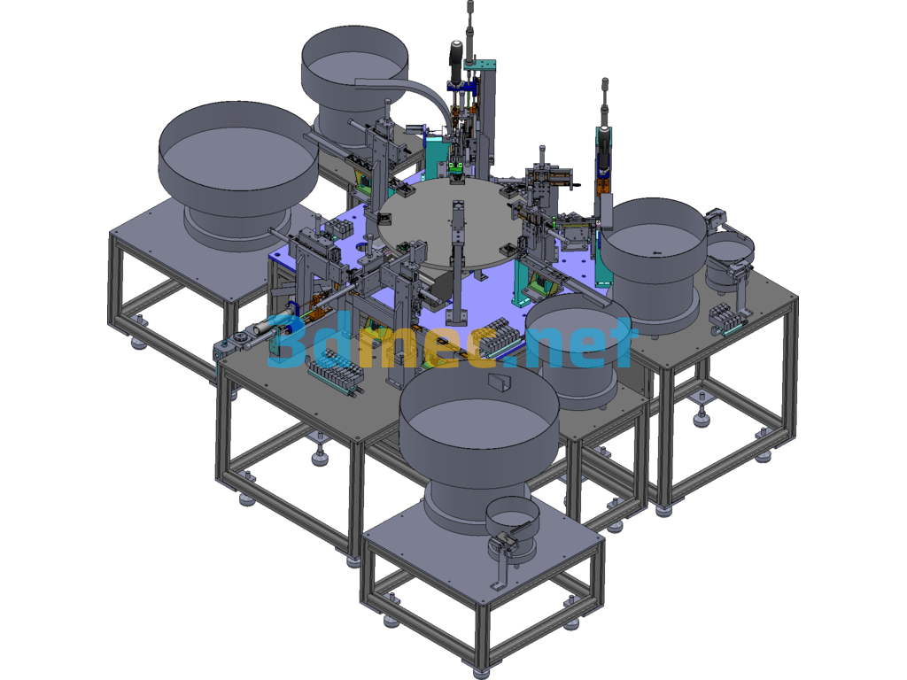
This set of circlip machine model is a micro-motor rotor bearing position circlip assembly tooling, which is used in a link in the rotor processing process of motor manufacturers. After the rotor is riveted into the shaft, the E-type circlip is pressed into the circlip groove through the tooling. The machinability of the rotor circlip guide bar of this set of structures has been greatly optimized after multiple optimizations, and the processing cost has also been reduced by 50%. The guide bars of the arc section processed by the lathe are assembled into integral guide bars to avoid excessive thickness of the wire cutting parts and subsequent bending processes, reducing the difficulty and making the circlip smoother. By integrating the propulsion cylinder into the circlip fixing seat, it is convenient to switch models on the production line.
Specification: Micromotor Rotor Retaining Spring Tooling – 3D Model SolidWorks
|
User Reviews
Be the first to review “Micromotor Rotor Retaining Spring Tooling – 3D Model SolidWorks”
You must be logged in to post a review.





There are no reviews yet.