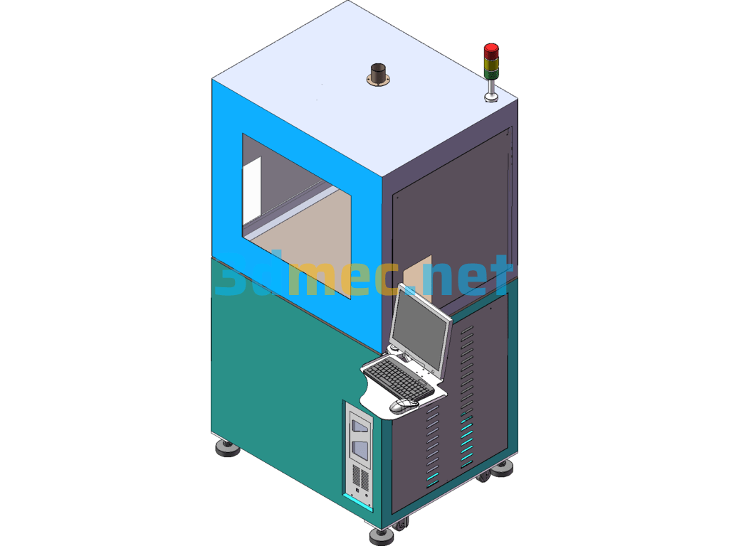
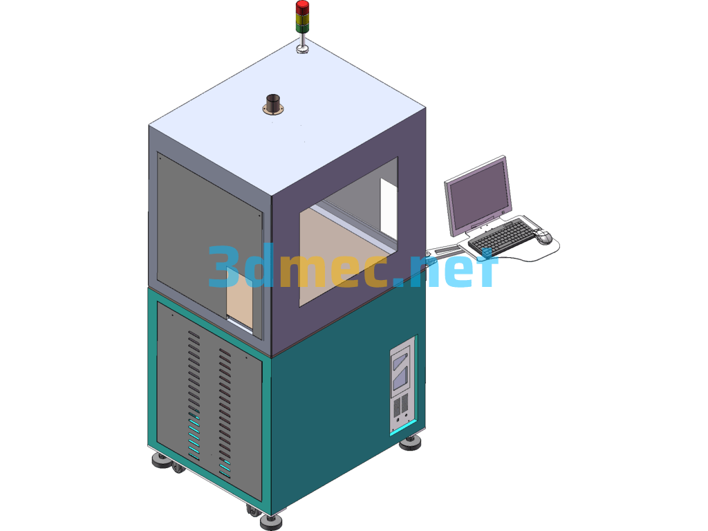
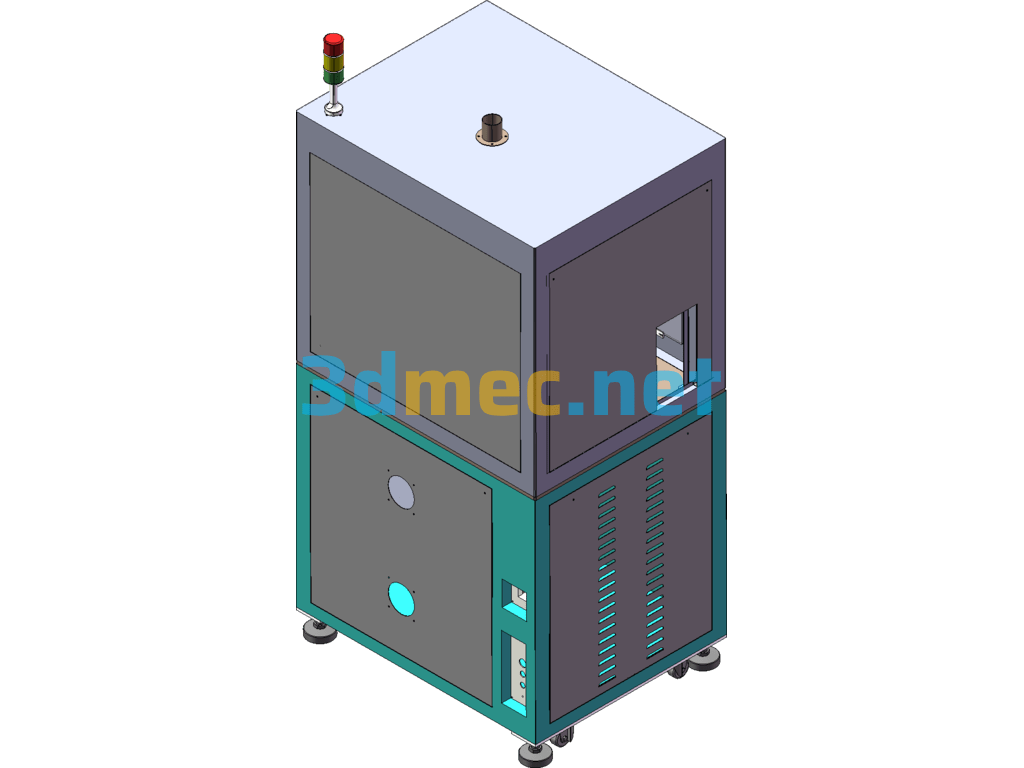
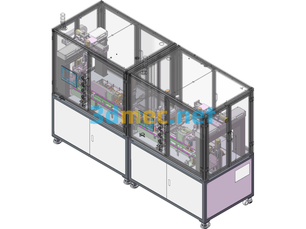
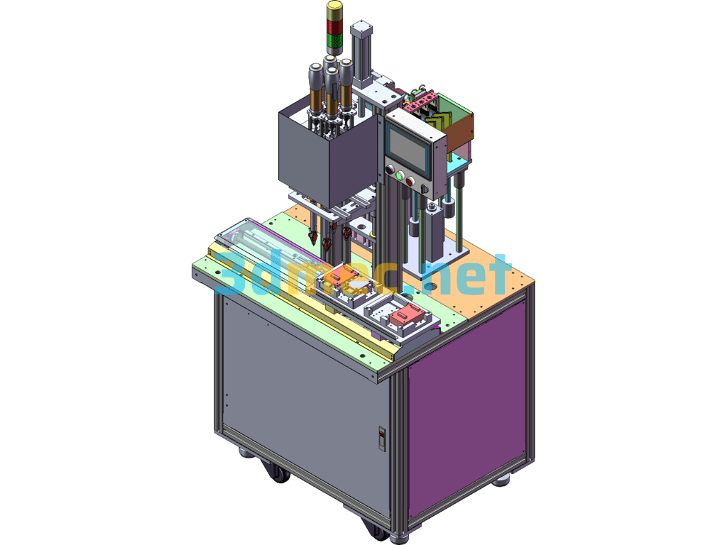
Laser marking equipment action flow:
1.Manually put the product on the left side of the equipment.
2.The product enters the equipment and is automatically marked on the front and back sides.
3.The marked products are collected from the belt line on the right side of the equipment.
4Manually put the products on the left side one by one.
5.After the sensor detects that the first six products are full, the clamping cylinder clamps the product.
6.The blocking cylinder prevents the clamping jaws from colliding with the seventh product when clamping the first six products.
7.The electric cylinder drives the two sets of clamping jaws to move synchronously, and the two actions of grabbing and collecting materials are performed synchronously.
8.Clamping jaw 1 clamps the 6 products on the left and puts them into the marking position, and the machine automatically marks the front and back sides.
9.Clamping jaw 2 clamps the finished product and puts it into the belt line on the right. After the sensor detects that the product is in place, the belt line runs and the product is collected.
Specification: Laser Marking Equipment – 3D Model SolidWorks
|
User Reviews
Be the first to review “Laser Marking Equipment – 3D Model SolidWorks”
You must be logged in to post a review.




There are no reviews yet.