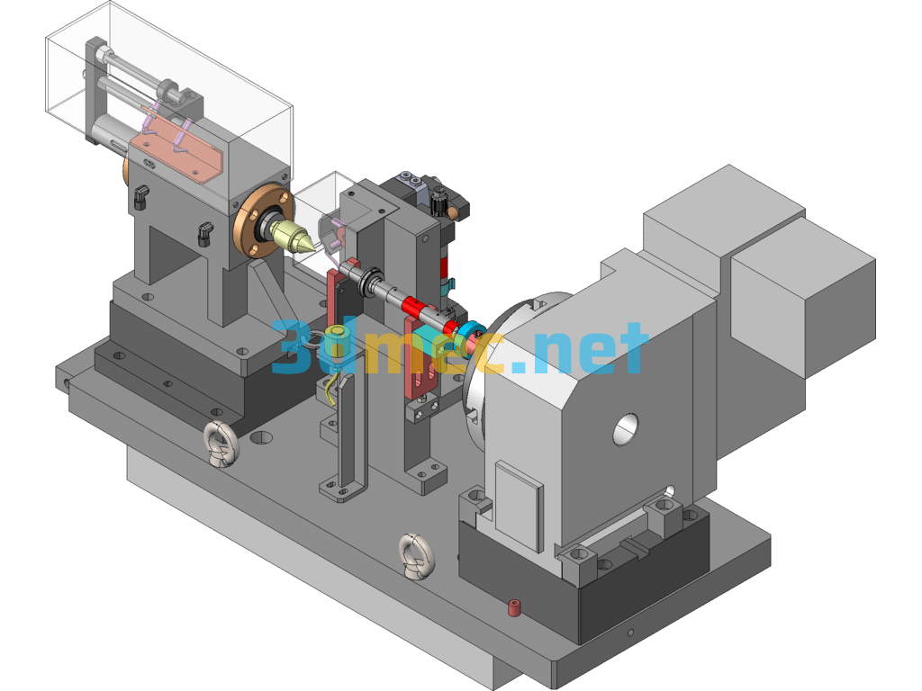
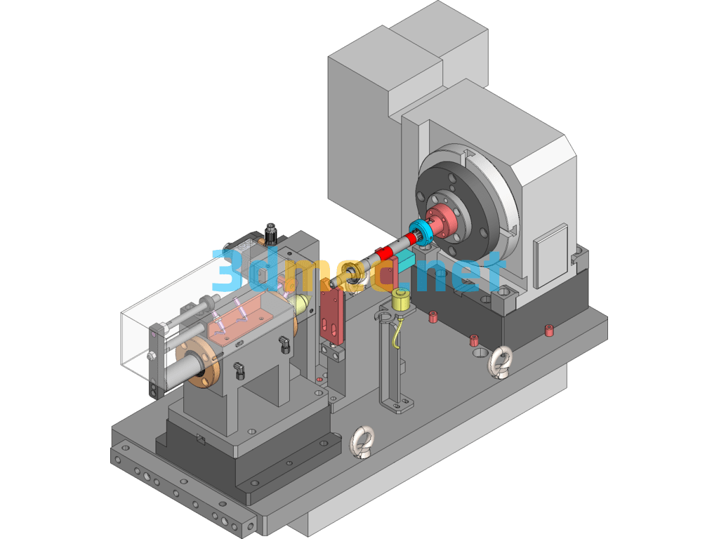
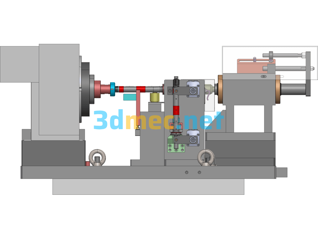
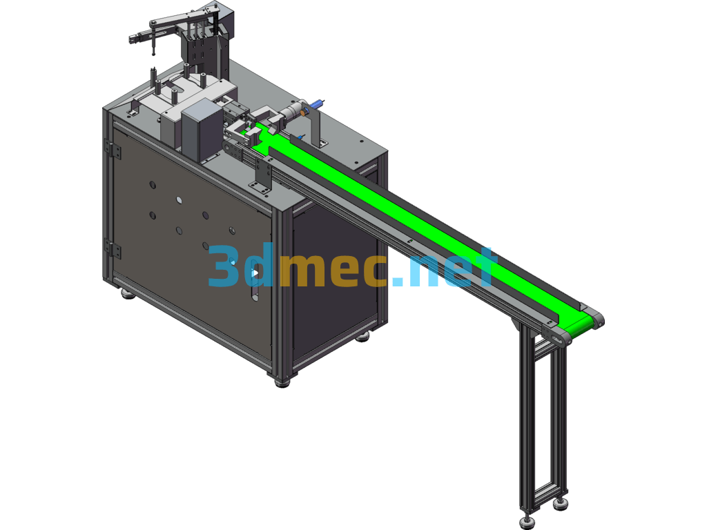
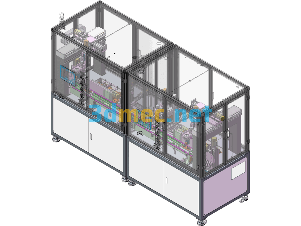
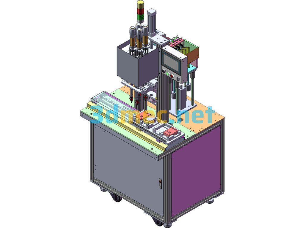
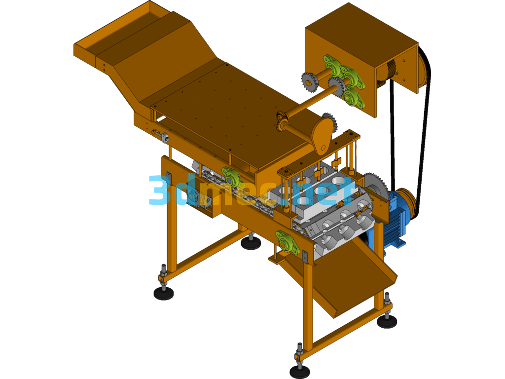
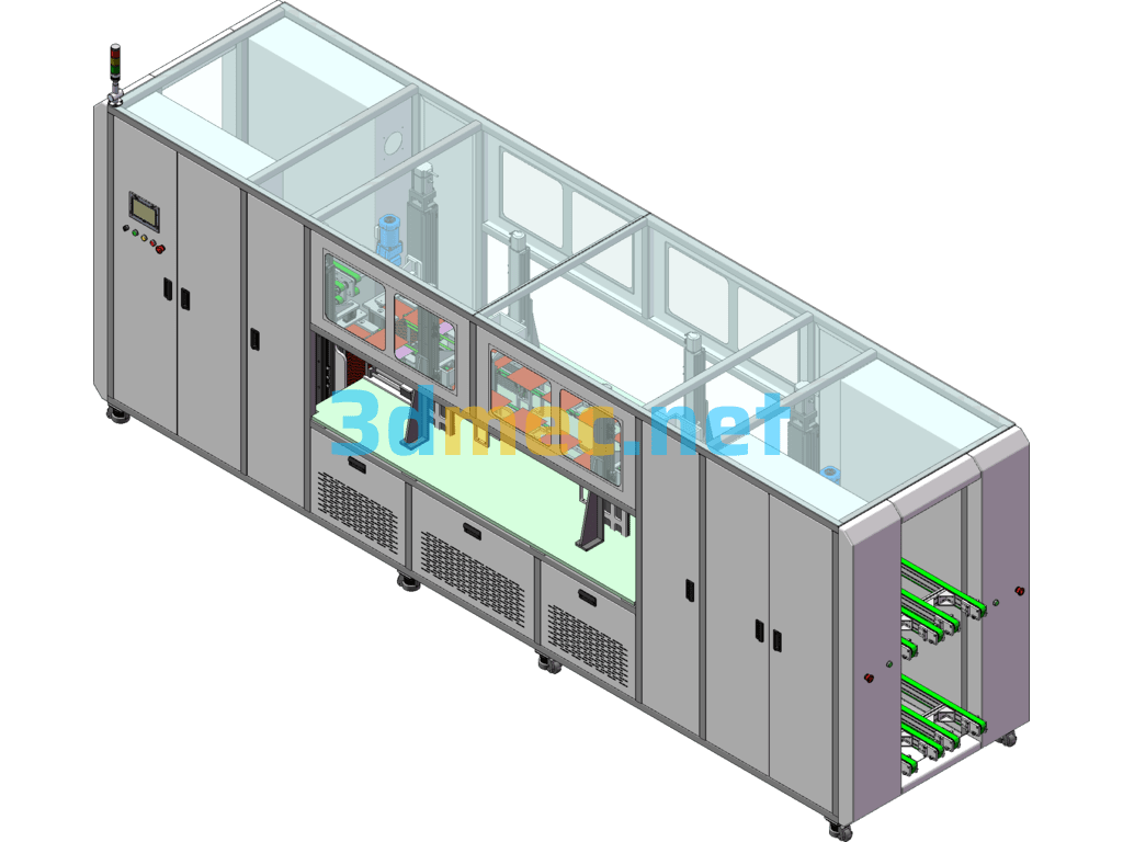
Intermediate Shaft Hydraulic Fixture Assembly Diagram SolidWorks 3D Model

Add to wishlistAdded to wishlistRemoved from wishlist 0
Sold by
MrBlue
@
Deprecated: Function bp_core_get_user_domain is deprecated since version 12.0.0! Use bp_members_get_user_url() instead. in /home/3dmec.net/public_html/wp-includes/functions.php on line 6078
MrBlue

This picture is the intermediate axis hydraulic fixture assembly diagram, with machine tool CMV-510A, table size 600X360; this fixture OP10 using workpiece center axis and spline end face positioning; OP20 using V-block fixed workpiece center axis and bottom end face positioning; OP10 oil circuit: 1 inlet and 1 outlet; OP20 oil circuit: 1 inlet and 1 outlet; rotary table brakes 1 way; fixture weight is about: 250KG.

Specification: Intermediate Shaft Hydraulic Fixture Assembly Diagram SolidWorks 3D Model

Industrial Use

Machinery & Equipment

Design Software

SolidWorks

Version

2012

Editable

Editable, With Parameters

File Formats

Sldasm, Slddrw, Sldprt, step(stp)

Sharing Level

SVIP

Project's Download Info

User Reviews

0.0 out of 5
0
0
0
0
0
Write a review

There are no reviews yet.

Be the first to review “Intermediate Shaft Hydraulic Fixture Assembly Diagram SolidWorks 3D Model”

Intermediate Shaft Hydraulic Fixture Assembly Diagram SolidWorks 3D Model
3D Mechanical Design Library
Logo
Shopping cart