Fuse Box Automatic Testing Machine – 3D Model SolidWorks
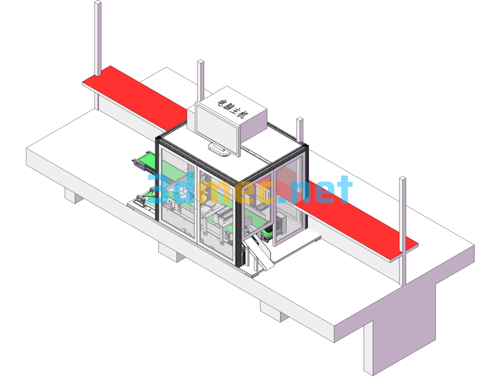
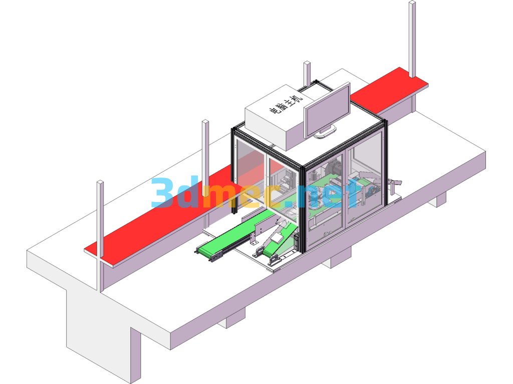
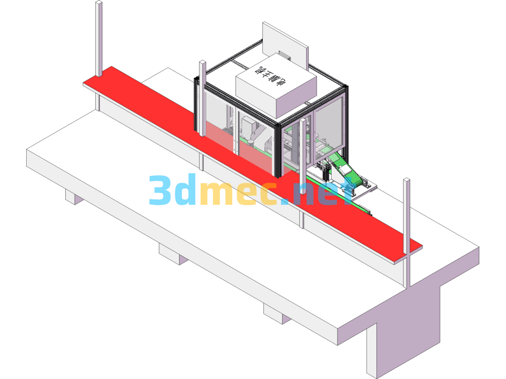
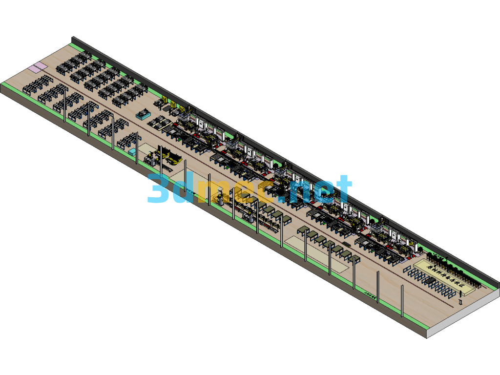
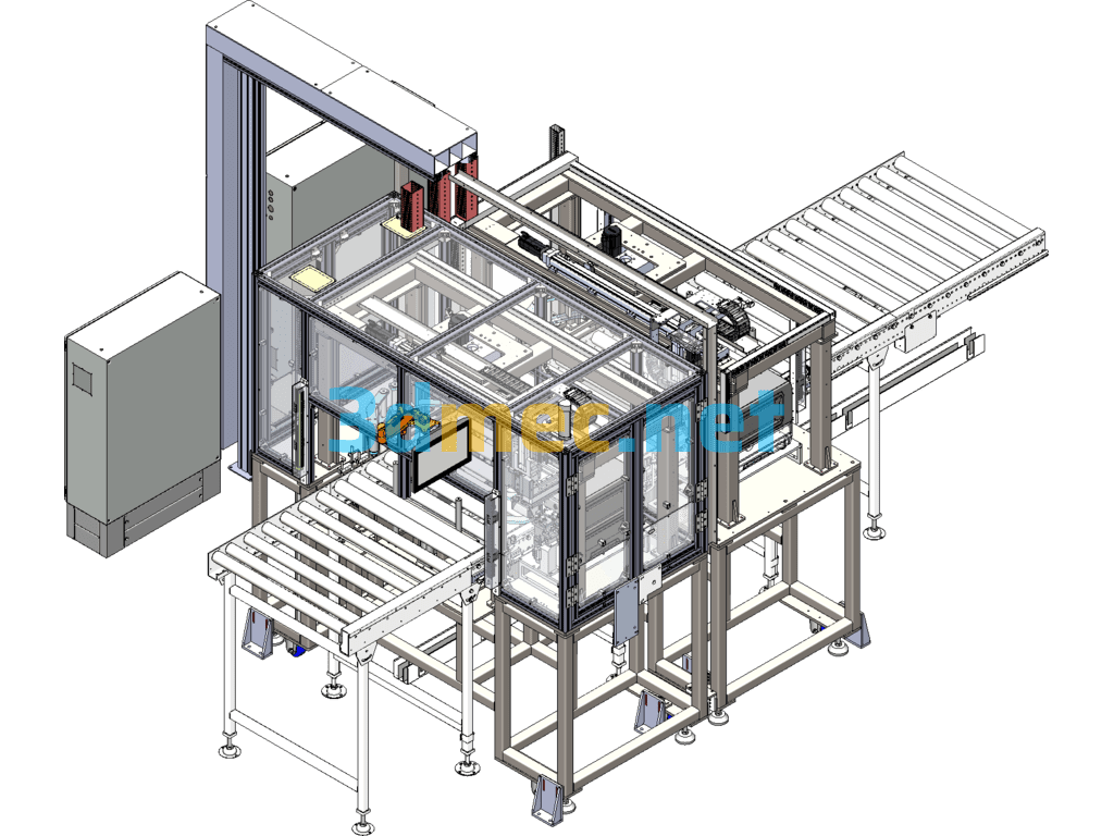
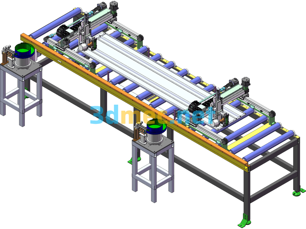
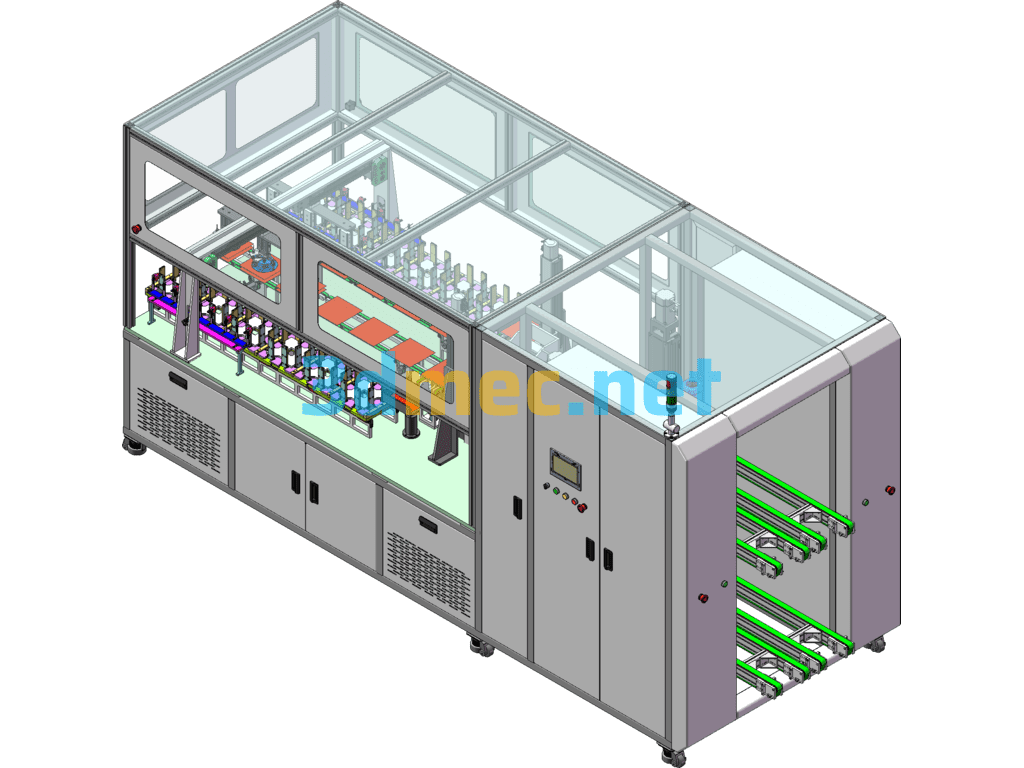
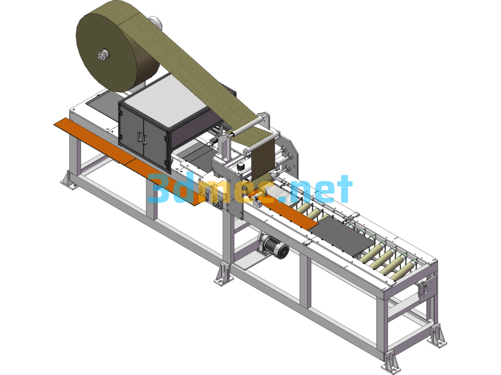
The automatic inspection machine for fuse boxes includes 3D models, standard parts blanking list BOM table, photos and videos of fuse box production line, fuse box detection distance diagram, machine design manual, detection distance diagram, etc
System composition overview: The system mainly consists of the following 6 parts
1. Manual feeding system: Manually place the fuse box on the conveyor belt very conveniently, so that the fuse box can enter the inspection system in an orderly manner to realize the feeding function.
2. Conveying motion system: It is composed of motors, conveyor belts, controllers and related accessories to realize the smooth transportation of fuse boxes according to the requirements of the inspection system.
3. Visual inspection system: It is composed of 2 sets of cameras and corresponding light sources. The specific inspection items are shown in “Appendix 1”.
4. Software analysis control system: After the camera takes the image, the host software analyzes it and determines the properties of the fuse box: qualified products or unqualified products;
5. Discharging sorting system: After the software determines the properties of the fuse box, the PLC electrical control system is used. The discharging sorting system classifies and discharges the fuse boxes into qualified products and unqualified products according to the properties indicated by the software.
6. PLC electrical control system: The control action of the entire set of equipment is completed through the combination of PLC and electrical control components.
Specification: Fuse Box Automatic Testing Machine – 3D Model SolidWorks
|
User Reviews
Be the first to review “Fuse Box Automatic Testing Machine – 3D Model SolidWorks”
You must be logged in to post a review.



There are no reviews yet.