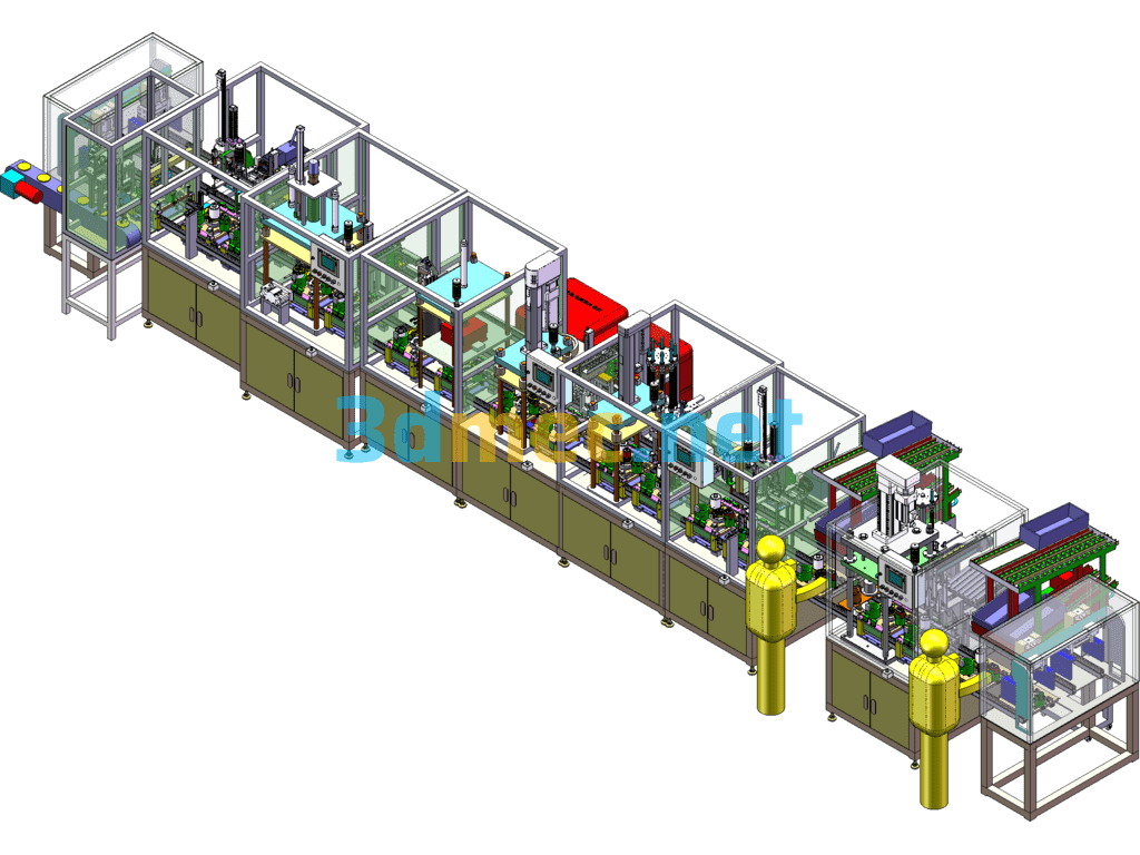
Fully Automatic Stator Shaft Assembly Line, Large Non-Standard Assembly Line – 3D Model SolidWorks
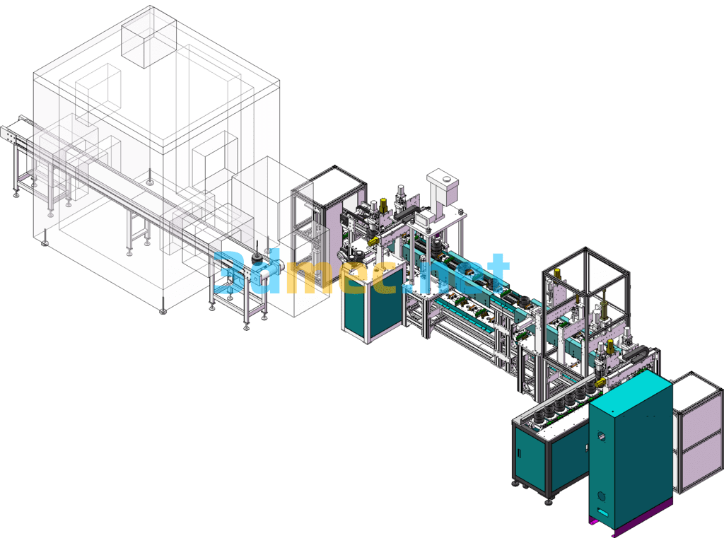
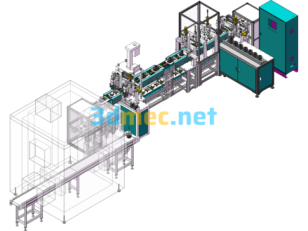
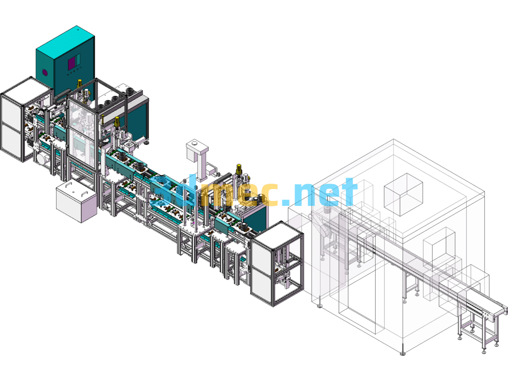
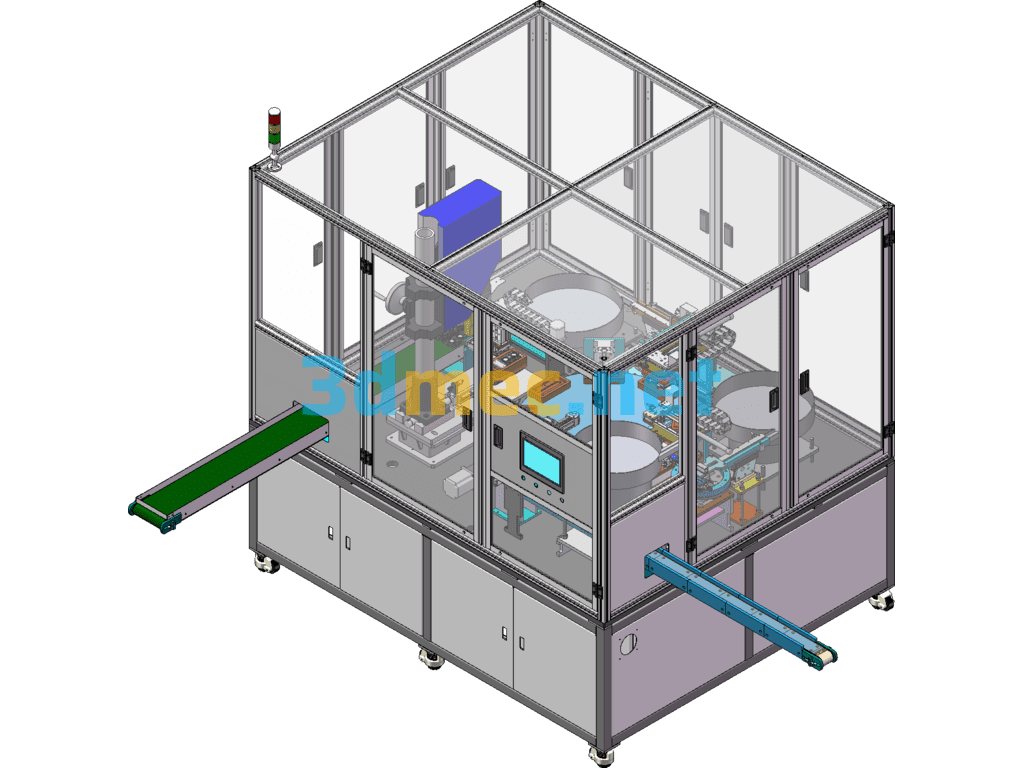
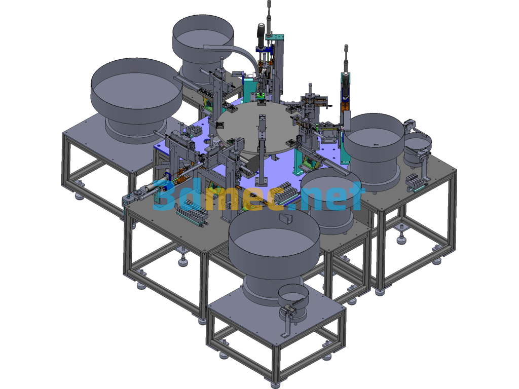
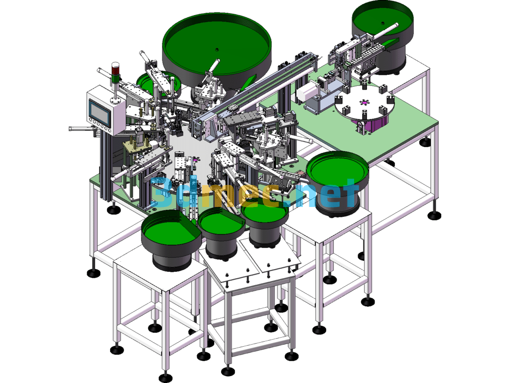
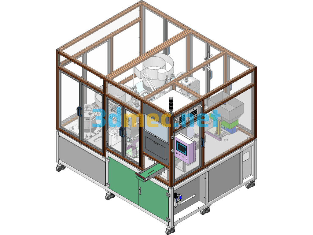
Fully automatic stator shaft assembly line, this model contains engineering drawings and list bom. It is a large non-standard assembly line, which automates the assembly of various complex parts of non-standard assembly production lines.
Non-standard automatic production line Fully automatic stator shaft assembly line working principle and action sequence:
A. The special tooling board enters the tooling board storage area from the lifting platform.
B. When the tooling board for placing the BMC stator is empty, the tooling board enters the station from the storage area. (The blocker blocks the tooling board, and the tooling board stops, the same below) The manipulator puts the BMC stator (a total of 2 sets) into the corresponding positions of the special tooling board, steps on the foot switch, and the tooling board goes down and enters the next storage area.
C. When the station for placing the rotor, PG board and BB cover is empty, the tooling board automatically enters the station, and then the foot switch is stepped on, and the tooling board automatically runs to the next station temporary storage area.
D. When the BB cover pressing station is empty, the tooling board automatically enters the station to automatically press the BB cover to detect the amount of movement, etc. After pressing, the foot switch is stepped on and the tooling board automatically moves to the next station for temporary storage.
E. When the performance test station is empty, the tooling board automatically moves to this station to manually test the performance. After the performance test is completed, the foot switch is stepped on and the tooling board automatically moves to the tooling board lifting platform stacking area.
F. Execute the next cycle.
3. The total length of the line is 5 meters (including the lifting platforms at both ends) (subject to the actual design), the total width is 300mm (subject to the design size) (excluding the protruding parts of the lifting platforms at both ends), the upper layer including the tooling board is 800 mm (subject to the actual design), and the height between the two layers is 400mm (subject to the actual design). The support bracket of the line body is height adjustable, with an adjustment range of ±30mm.
4. The line body adopts a double-layer return plate structure, the upper layer is used for motor transmission, and the lower layer is used for tooling plate fast return plate.
a. The line body is driven by roller chain; it is driven by independent power.
Specification: Fully Automatic Stator Shaft Assembly Line, Large Non-Standard Assembly Line – 3D Model SolidWorks
|
User Reviews
Be the first to review “Fully Automatic Stator Shaft Assembly Line, Large Non-Standard Assembly Line – 3D Model SolidWorks”
You must be logged in to post a review.



There are no reviews yet.