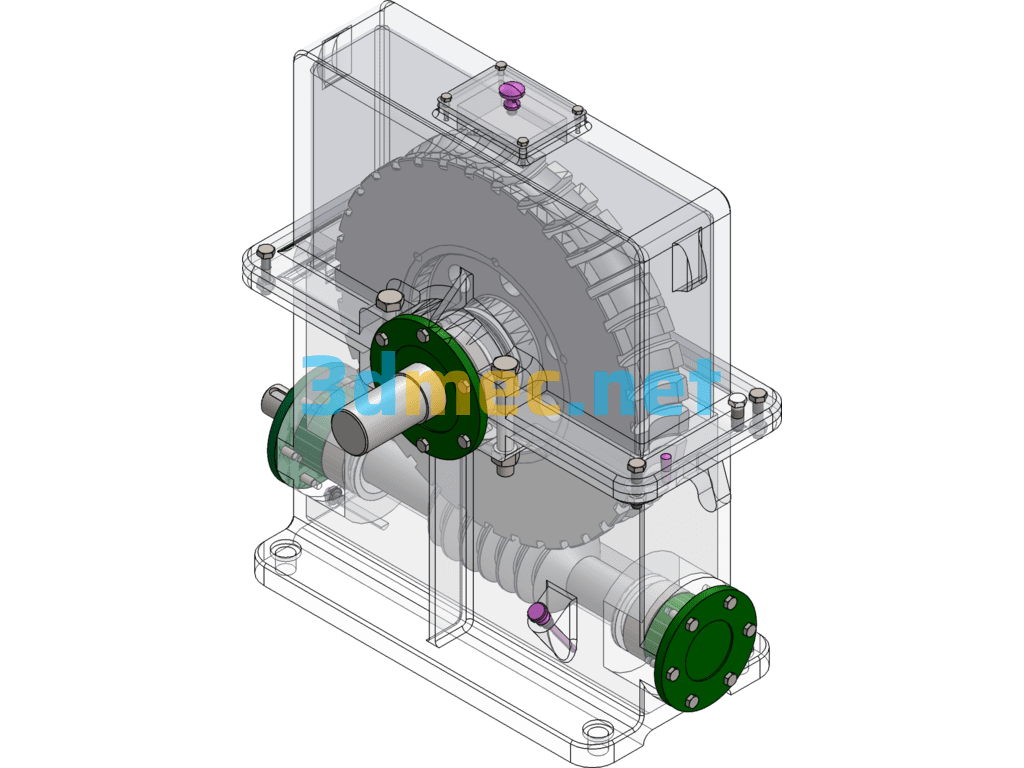
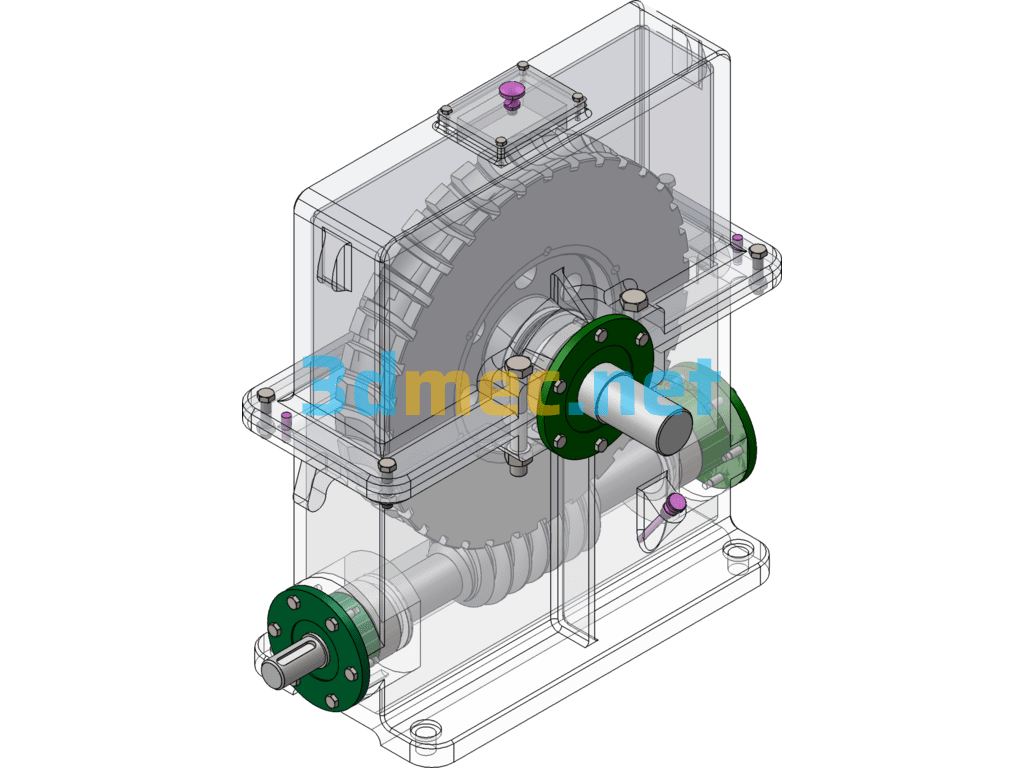
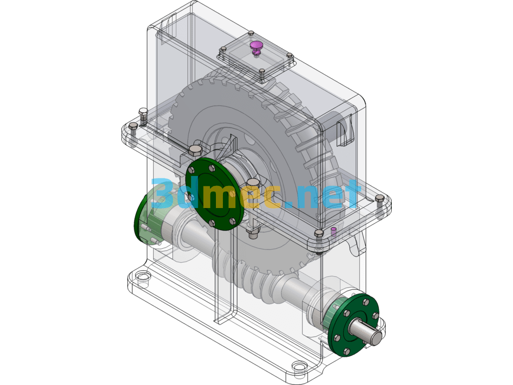
First-Stage Worm Gear Reducer, First-Stage Worm Gear Inlet And Outlet Coupling F=2500 V=1.0 D=350 10X2 Plus Instruction Manual CAD – 3D Model SolidWorks
Worm gear mechanisms are often used to transmit motion and power between two staggered axes. The worm wheel and worm are equivalent to the gear and rack in their middle plane, and the worm is similar in shape to the screw.
With instruction manual
Specification: First-Stage Worm Gear Reducer, First-Stage Worm Gear Inlet And Outlet Coupling F=2500 V=1.0 D=350 10X2 Plus Instruction Manual CAD – 3D Model SolidWorks
|
User Reviews
Be the first to review “First-Stage Worm Gear Reducer, First-Stage Worm Gear Inlet And Outlet Coupling F=2500 V=1.0 D=350 10X2 Plus Instruction Manual CAD – 3D Model SolidWorks”
You must be logged in to post a review.



There are no reviews yet.