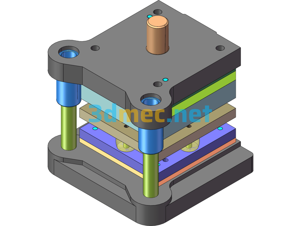
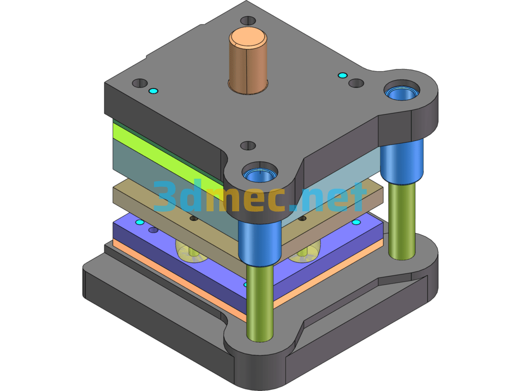
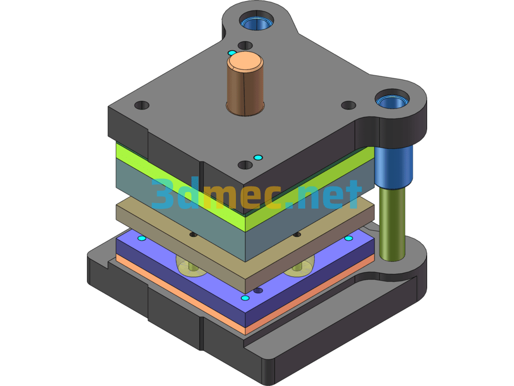
Design Of Compound Mold For Connecting Plate – 3D Model SolidWorks
Material: 08 steel material thickness: 2.0mm Batch: Large batch without dimension tolerance IT6
This set of molds is a composite mold for connecting the power strip. The drawings include CAD assembly drawings and parts drawings, UG three-dimensional drawings, complete drawing parts, and drawing specifications.
1. The punch is installed by pressing in. First grind the punch and then connect it with the pad;
2. The guide sleeve and the guide column are clearance fit H7/h6. Pay attention to correcting the verticality of the guide column, guide sleeve and template when pressing in; the distance between the fixed end face of the assembled guide column and the upper and lower die seat planes is 1~3mm;
3. The guide column and the lower die seat are interference fit H7/r6; the guide sleeve and the upper die seat are H7/r6;
Specification: Design Of Compound Mold For Connecting Plate – 3D Model SolidWorks
|
User Reviews
Be the first to review “Design Of Compound Mold For Connecting Plate – 3D Model SolidWorks”
You must be logged in to post a review.



There are no reviews yet.