D077 Instrument Panel Punching Equipment – 3D Model Exported


Table of contents of instrument panel punching machine
I. Overview1
II. Main technical parameters1
2.1 Overall parameters1
2.2 Working environment1
III. Equipment composition1
3.1 Mechanical part1
3.2 Pneumatic system2
3.3 Electrical system3
IV. Operation and use3
4. 1 Operation preparation………………………………………………………………………………………………….3
4. 2 Electrical operation…………………………………………………………………………………………….3
4. 3 Manual mode………………………………………………………………………………………………………………..4
4. 4 Automatic mode………………………………………………………………………………………………………………..5
4. 5Parameter setting………………………………………………………………………………………………………………..6
V. Operation process6
VI. Maintenance and repair6
6.1 Maintenance and repair of mechanical parts7
6.2 Maintenance and repair of pneumatic system7
6.3 Maintenance and repair of control system7
VII. Installation instructions7
VIII. Accessories/wearing parts/spare parts7
IX. Provide information8
X. Appendix (electrical schematic diagram)………………………………………………………………………………………8
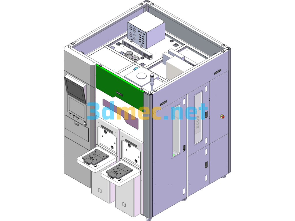
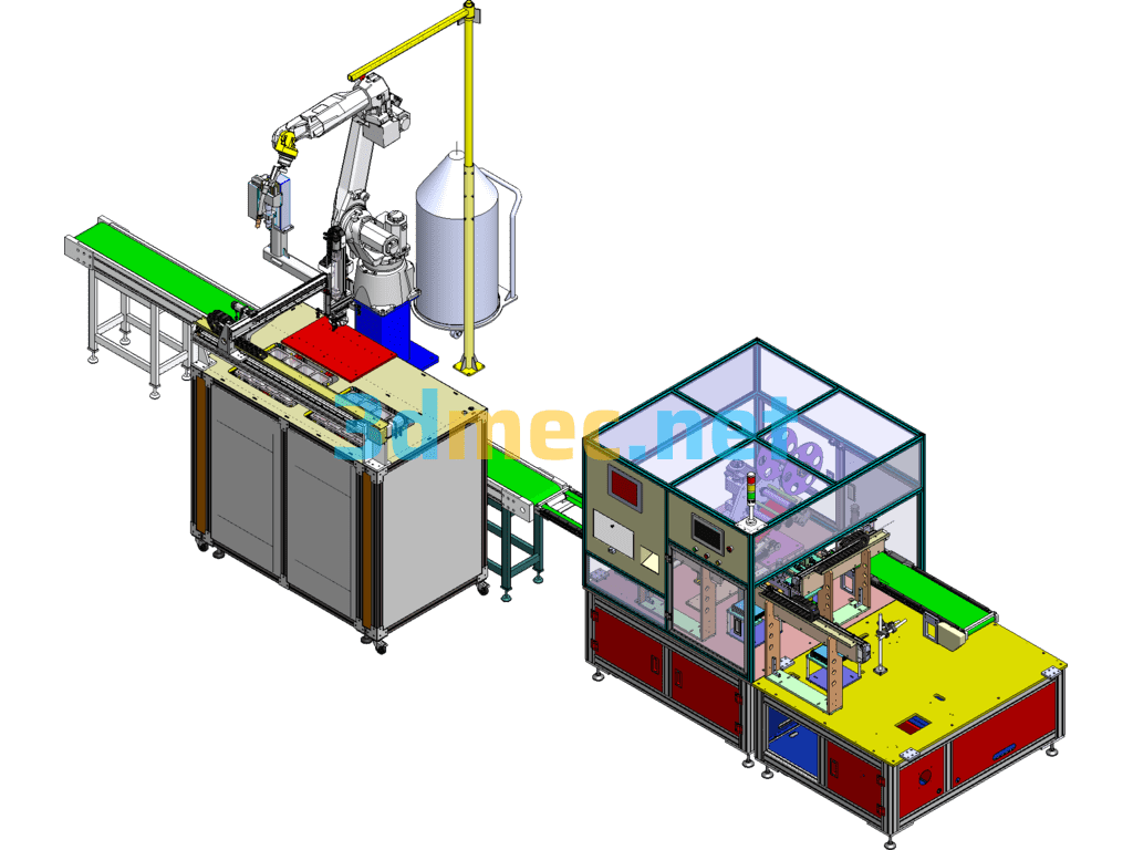
I. Overview
This equipment is used in production workshops, mainly for punching vents on both sides of D077 products and drilling Ø7 harness holes on the front. This equipment is not suitable for other products except D077 products. Punching is automatic and drilling is semi-automatic.
II. Main technical parameters
2.1 Overall parameters
Equipment model: ZKBC-WL-001
Maximum dimensions: 2900mm×1650mm×2200mm (length×width×height)
Total weight: about 4.5 t
Motor power: 2.5 kW
Maximum output force of gas-liquid cylinder: 10t
Heating temperature: less than 60℃
Production cycle: 110 seconds/piece
Noise: ≤60db
2.2 Working environment
Power supply voltage: AC220V±10%; 50Hz±2%
Relative humidity: ≤95%RH
Working temperature: 0~40℃
Compressed air pressure: 0.6MPa
III. Equipment composition
The main components of this equipment can be divided into mechanical part, pneumatic system and electrical system.
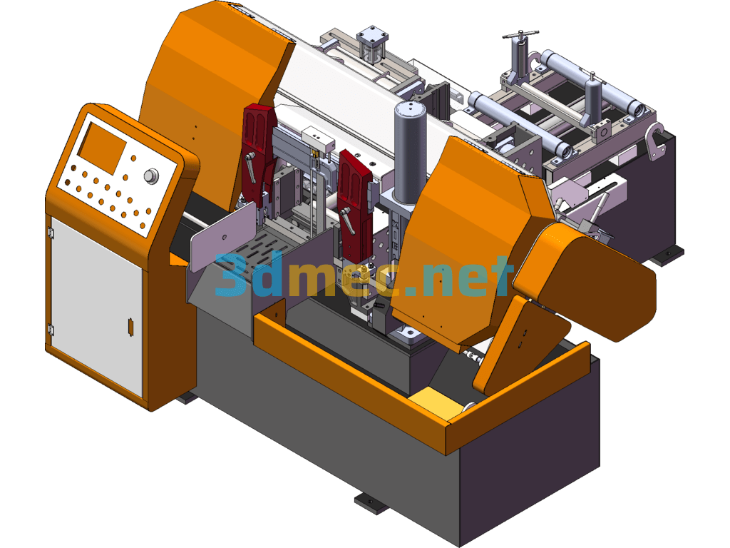
3.1 Mechanical part
This equipment is mainly composed of base, servo motion system, positioning mechanism, stamping system, temperature control system and drilling mechanism.
3.1.1 Base
The base is made of 120×120 square steel pipe and 50mm thick iron plate, which can withstand large external force and ensure that the equipment does not deform during stamping and use. The base uses adjustable foot support, and the height can be adjusted up and down by 100mm.
3.1.2 Private service motion system
The private service motion system is mainly composed of servo motor ball screw mold and clamping cylinder. The servo motor and ball screw are connected by coupling, and the accuracy of the motion part can reach 0.015mm. The jig is equipped with a sensor to detect the presence of the product. The equipment cannot be started without the product installed. When placing the product, ensure that each positioning point is accurately positioned and the product is placed in place to avoid interference with other parts during movement.
3.1.3 Positioning mechanism
The positioning mechanism consists of two ejection cylinders and positioning sleeves and positioning pins installed on the base of the equipment. The positioning mechanism plays the role of secondary positioning of the jig and bearing the lateral shear stress of the system. It can improve the positioning accuracy of the jig and protect the linear guide rail and ball screw.
3.1.4 Stamping system
The stamping system is the main part of the equipment stamping, which includes two separate parts on the left and right. The two parts are fixed to the base of the equipment with a gantry beam. Each part includes a gas-liquid booster cylinder floating joint assembly, a guide column, a guide sleeve and a punch.
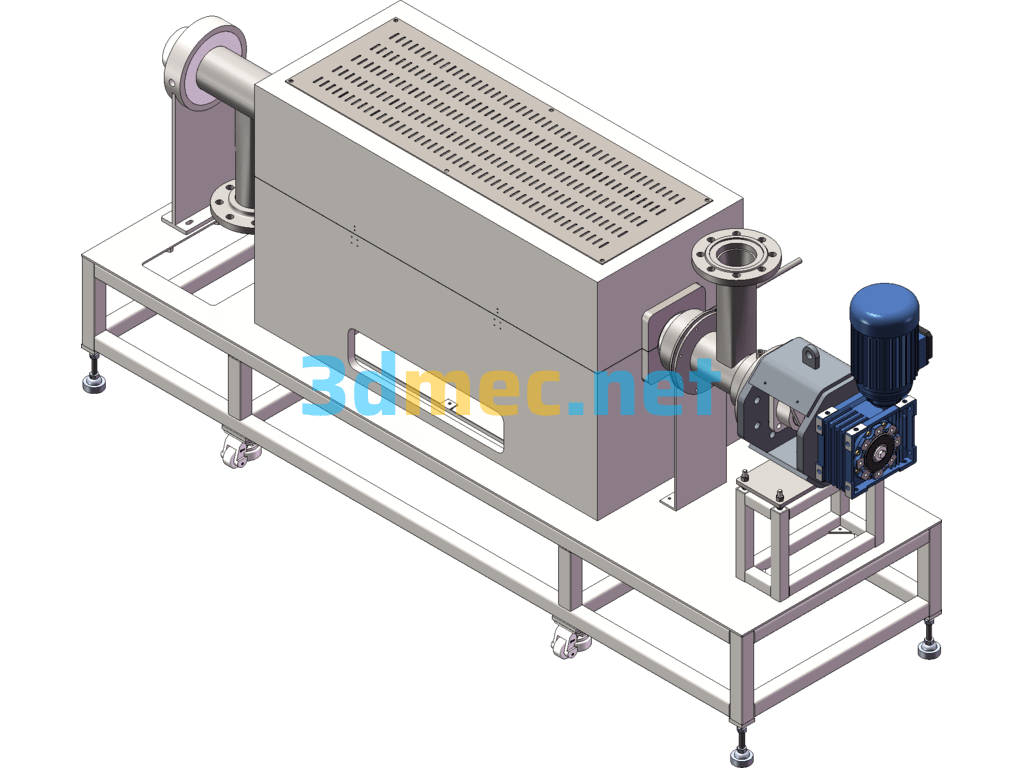
3.1.5 Temperature control system
The temperature control system consists of a heating plate, a heating rod and a temperature sensor. The function of the heating system is to heat the punch, changing from cold cutting to hot cutting to reduce cutting edge burrs. The heating temperature of the heating system is less than 60℃, and the resolution of the temperature sensor is 0.1℃.
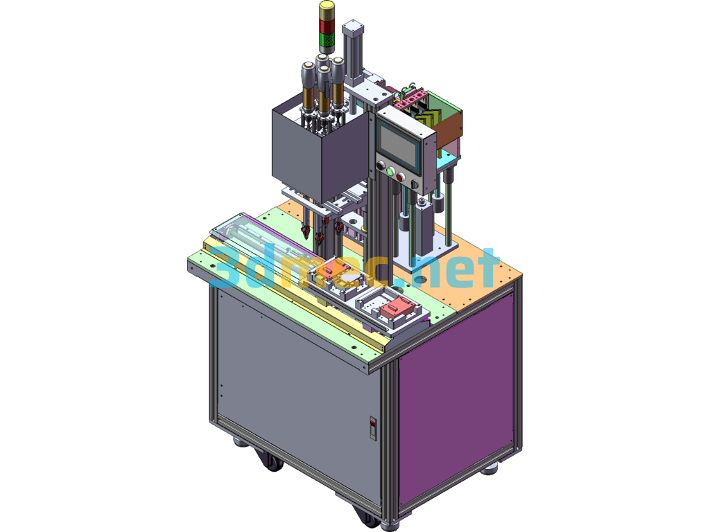
3.1.6 Drilling mechanism
The drilling mechanism is a semi-automatic design, which includes rodless cylinder linear guide pneumatic drill linear bearing and buffer. The left and right movement of the mechanism is automatic, and the drilling action is manual.
3.2 Pneumatic system
The pneumatic system mainly plays the role of control and positioning.
The air source processing part includes filtering, oil-water separation and pressure adjustment functions. The control part is mainly an electromagnetic reversing valve, which is centrally controlled by a programmable controller (PLC). The user can control the action of the actuator by operating the button. The actuator is a cylinder, and the positioning and stamping functions are realized through the movement of the cylinder.
3.3 Electrical system
This system consists of a servo motor, a servo controller, a PLC, etc., and is controlled by the PLC. For details, please refer to the electrical schematic diagram and the program flow chart.
IV. Operation and Use
4.1. Operation Preparation:
1) Before use, check whether all parts in the system are in the correct position.
2) Whether the oil level of the gas and liquid cylinder is within the indication range of the liquid level gauge.
3) Whether the pipe interfaces and fastening screws are loose.
4) Whether the rear maintenance door is closed.
5) Whether all moving parts are in their original positions;
6) Check whether there are people and debris at the workstation. No one can be under the equipment.
If everything is normal, it can be put into operation. During the use of the equipment, no debris can be piled in the workstation, and no one can enter under the equipment. If any abnormality is found during operation, the machine should be stopped for inspection and put into operation after the fault is eliminated.
4.2 Electrical operation
1. Before debugging, the operator shall check all parts of the equipment to ensure that the equipment debugging is carried out normally.
2. Grounding: The equipment should be grounded to protect the equipment, and the grounding resistance should be less than 0.5 ohms.
3. After all power lines and pneumatic pipelines are connected, turn on the main power supply and close the air switch on the equipment electrical box.
4. Close the short circuit in the distribution box to supply power to the equipment.
5. Rotate the equipment power-on key switch on the panel, press the power-on button on the panel, and power on.
6. Wait for the equipment to start up. Under normal circumstances, it takes 30 seconds to start up.
7. Startup completion mark:
After the startup screen ends, it automatically jumps to the manual or automatic screen.
Note:
The screen displayed after the power-on is completed is determined by the state of the manual-automatic conversion switch.
When the reset indicator on the panel is on for a long time, check whether the system status display window prompts an error message.
4.3 Manual mode
1. Select the “Manual/Automatic” selection switch to manual, and the screen will jump to the manual screen. Select the corresponding execution state in the manual screen, and then press “Manual forward” and “Manual reverse” to operate.
2. In manual mode, you can set parameters and view each status bit.
3. Positioning:
(1) In manual mode, click “Clamping cylinder tightening and loosening”, press the manual forward button to put the clamping cylinder in the clamping state, click “Servo motor forward and backward”, press the manual forward or reverse button to run the motor to the punching position, click “Lifting cylinder lifting” and press the manual forward and manual reverse buttons to observe whether the lifting cylinder can be lifted and lowered freely. If there is any deviation, adjust the front and rear position of the motor.
Manual interface
(2) In manual mode, click “Servo adjustment” to enter the servo adjustment screen, ensure that the clamping cylinder is in the clamping state, the booster cylinder is in the rising state, and the lifting cylinder is in the descending state, and click “Data initialization” and “Positioning start” in sequence
When the device stops at the origin, record the number of pulses, divide the recorded number of pulses by 2900, and enter the result into the “Displacement setting” value input. (The factory setting is about 520mm)
Positioning adjustment
4.4 Automatic mode
1. Select “Manual/Automatic” selection switch to automatic, and the screen jumps to the automatic screen.
2. Put the workpiece on, press the two-hand start button, slide the cylinder into place, manually hold the start handle, and punch.
3. After punching, press the two-hand start button again, the sliding cylinder retracts, and the automatic operation starts. The automatic operation is fully protected by the grating. Do not block the grating. If it is blocked, press the reset button for 1 second and then release it, it will automatically return to the origin and start the operation.
4.5 Parameter setting
1. The parameters are set at the factory and cannot be changed at will.
2. The temperature alarm value must be greater than the upper limit of the temperature setting when it is set.
3. The password is 888888.
V. Operation process.
Start work Start the control cabinet and touch screen power supply Put the workpiece in Press the double-hand start button Drilling mechanism in place After manual drilling is completed, press the double-hand start button again Clamp the cylinder Clamp the jig to the working position Positioning mechanism ejects the positioning Stamping part Stamping part returns the positioning mechanism returns the jig to the original position Clamp the cylinder Open and remove the workpiece (see the electrical flow chart for more details)
VI. Maintenance and repair
The equipment should be kept clean and tidy, and no debris should be placed on the work surface; irrelevant personnel shall not touch the equipment at will.
Strictly abide by the relevant provisions of the manual to ensure accurate adjustment and operation.
During the operation of the equipment, detailed records should be made on the replacement of various components and accessories and the handling of faults to facilitate future repairs, maintenance and fault analysis.
6.1 Maintenance and repair of mechanical parts
All moving parts of the equipment (screws, linear guides, bearings, etc.) should be lubricated regularly. When the oil level of the booster cylinder is lower than the lowest mark, hydraulic oil should be injected in time.
6.2 Maintenance and repair of pneumatic system
Regularly check the pressure of the pneumatic triplex and drain the water in time. Check the pneumatic pipelines and joints for leaks and damages regularly. If any are found, replace them in time.
6.3 Maintenance and repair of control system
6.4.1 Always keep the inside and outside of the electrical box dry;
6.4.2 Perform inspection and maintenance of the electrical system every six months:
Remove dust from the distribution box and control box;
Check whether the wiring terminals are loose or falling off; especially for high-power connectors, prevent loosening and sparking, causing accidents;
Check whether the insulation of the wire is aging and cracking.
6.4.3 Electrical maintenance must be carried out by professionals;
VII. Installation instructions
After the equipment arrives at the construction site, the packaging box should be carefully opened, and the quantity of goods and damage should be carefully checked according to the packing list, and our company should be contacted in time.
After unpacking the pneumatic system, ensure that all exposed openings of each part are covered or wrapped, and they must not fall off before the equipment is installed and piping is installed to avoid contamination of the system.
Pay attention to safety during transportation. The crane or forklift should have sufficient load-bearing capacity. The surface paint layer should not be damaged during lifting and transportation.
The equipment should be installed in a dry and ventilated environment, away from strong electromagnetic interference and corrosive media.
Fix each part of the equipment firmly according to the design drawing. Do not loosen it to avoid affecting its performance.
VIII. Accessories/wearing parts/spare parts
Serial No. Name Model Quantity Manufacturer Remarks
1 Punch and blade non-standard 4 Homemade
2 Ball screw C-BSSH2510-800 1 set MISUMI
3 Pneumatic drill installation wrench YBLX-ME/8112 1 Juba
IX. Provide information
9.1 Three-dimensional diagram of equipment
9.2 Two-dimensional diagram of equipment
9.3 Pneumatic system diagram
9.4 Electrical schematic diagram
9.5 Instructions and certificates of important purchased parts
Appendix 1: Electrical schematic diagram
Main circuit schematic diagram
Servo motor schematic diagram
Servo controller schematic diagram
PLC input schematic
PLC input schematic
PLC output schematic 1
PLC output schematic 2
PLC output schematic 3
Analog input circuit
Electric control cabinet
Original layout diagram
Specification: D077 Instrument Panel Punching Equipment – 3D Model Exported
|
User Reviews
Be the first to review “D077 Instrument Panel Punching Equipment – 3D Model Exported”
You must be logged in to post a review.


There are no reviews yet.