Chip Grab Test Equipment (With PPT Equipment Process Explanation) – 3D Model SolidWorks
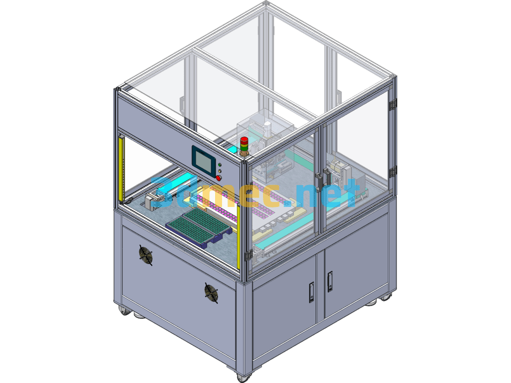
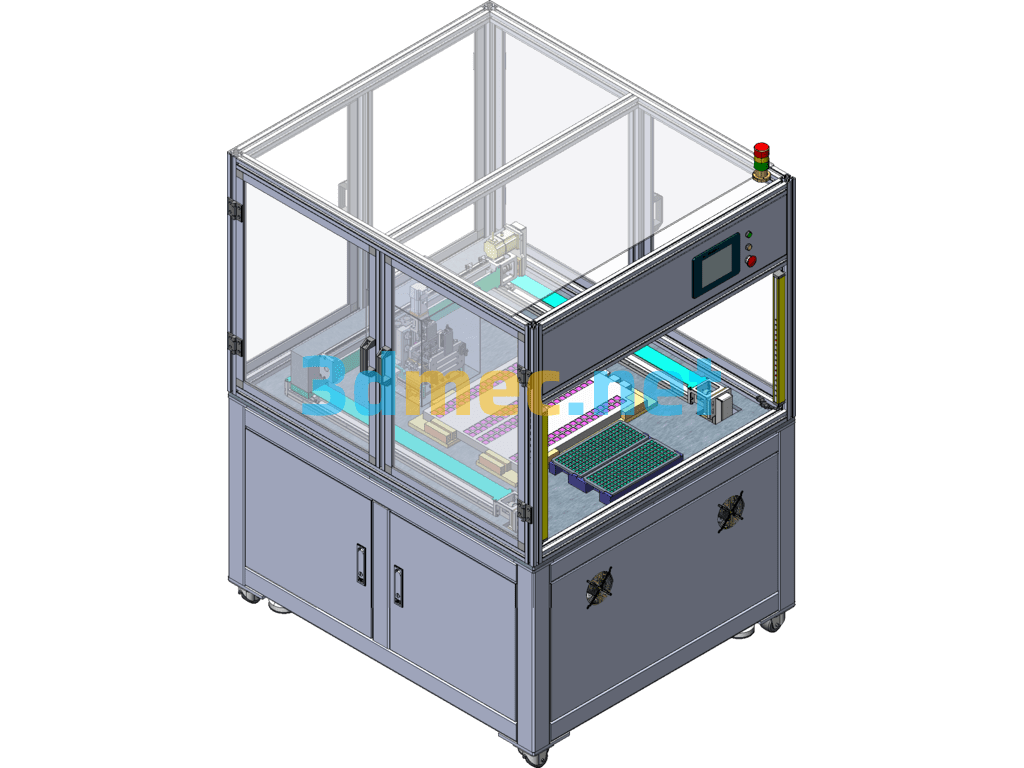
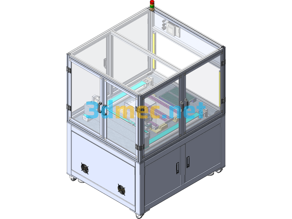
The chipset uses two groups of trays to switch and feed continuously. The 3-axis XYZ module is equipped with a bidirectional variable pitch module to absorb the product. After the pitch is changed, it is put into the test group for detection and automatically divided into OK/NG
Chip grabbing test equipment (with PPT equipment process explanation) Operation introduction:
1. Manually put in the circuit board, and the inner cavity guides the positioning;
2. Manually put in two groups of chip trays;
3. After the photoelectric detection of the loading is in place, the equipment is ready and the manual button starts the equipment;
4. The discharge pressure plate moves to avoid the position, and the suction nozzle changes the pitch and moves to the tray to absorb the material. After the pitch is changed, it is pressed down and loaded into the circuit board;
5. Reminder for unloading and changing materials;
6. Take out the empty tray and put in the new material tray. The equipment remembers the quantity and position of the other tray;
7. The discharge position can be selected separately for every two rows;
Specification: Chip Grab Test Equipment (With PPT Equipment Process Explanation) – 3D Model SolidWorks
|
User Reviews
Be the first to review “Chip Grab Test Equipment (With PPT Equipment Process Explanation) – 3D Model SolidWorks”
You must be logged in to post a review.



There are no reviews yet.