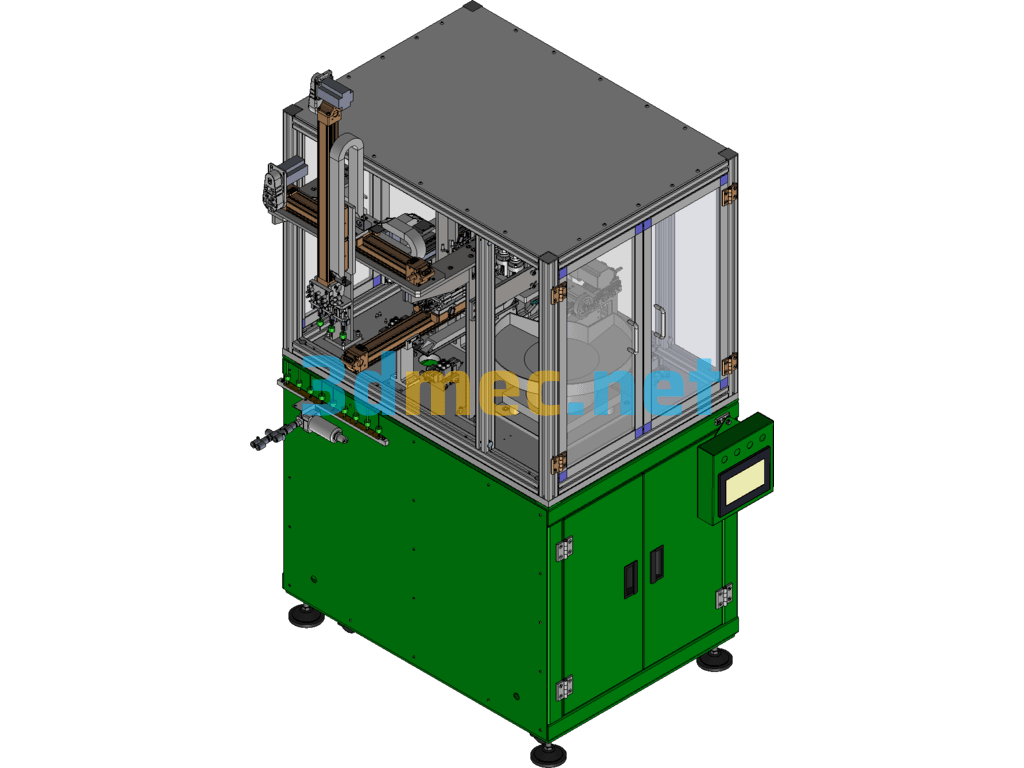
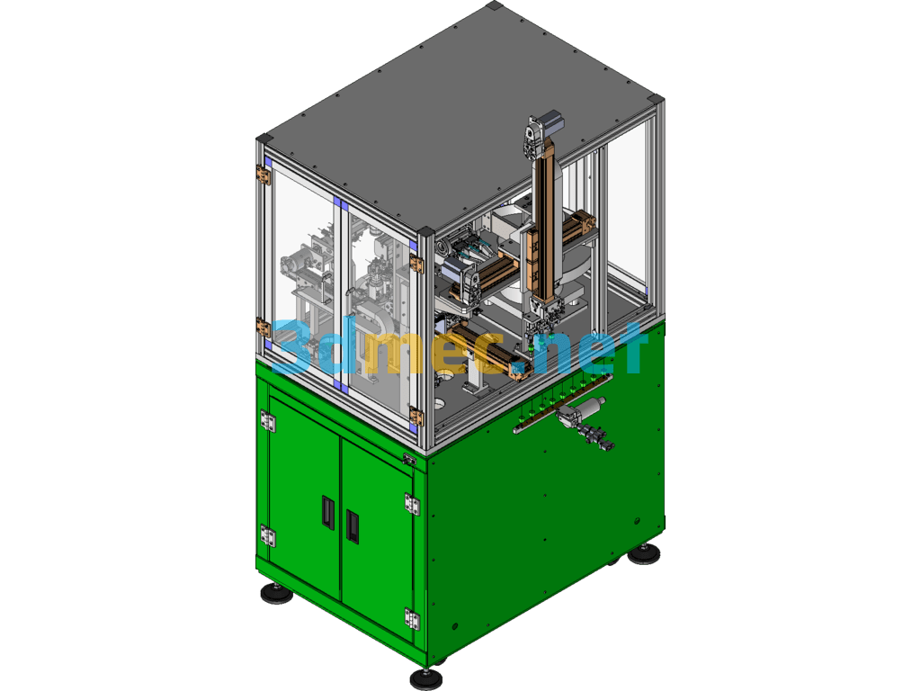
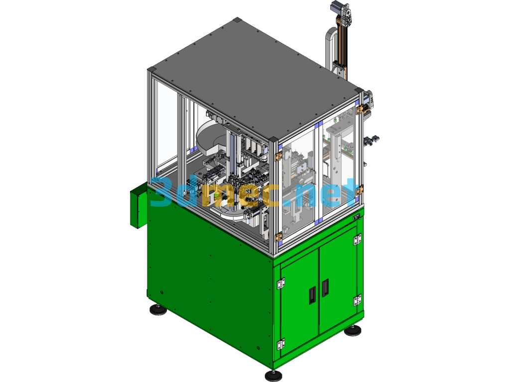
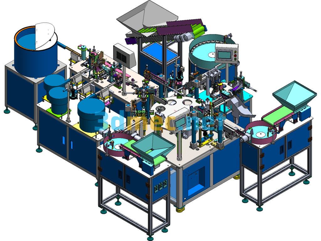
BD1901 Motor Rotor Commutator Assembly Machine – 3D Model SolidWorks
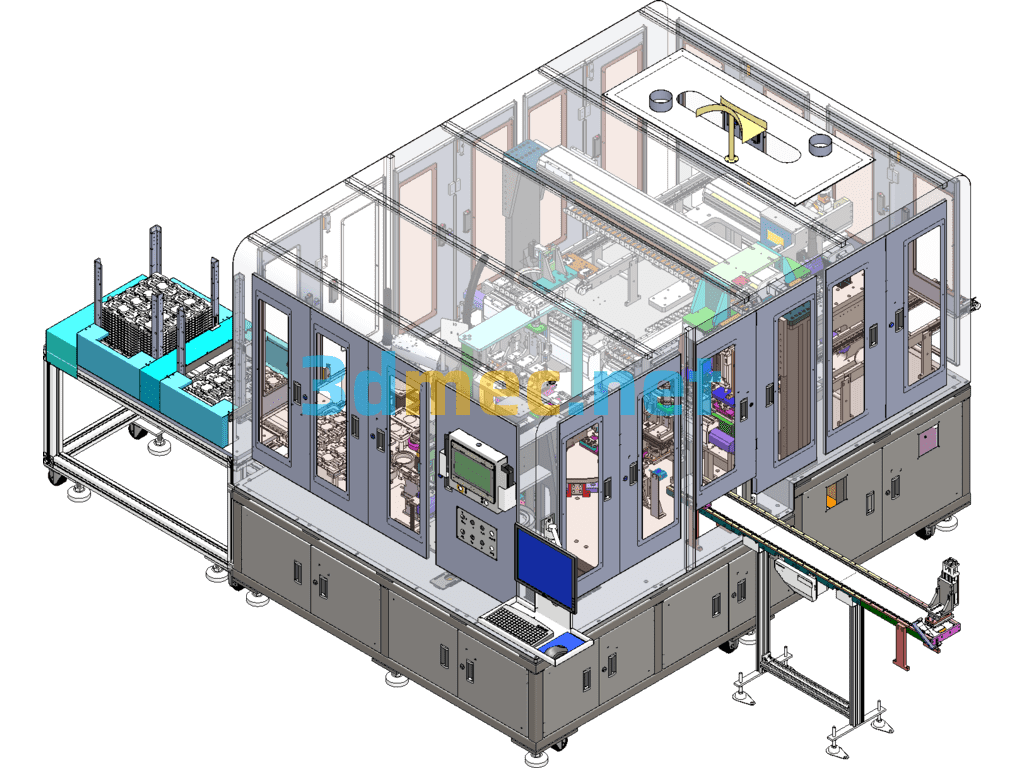
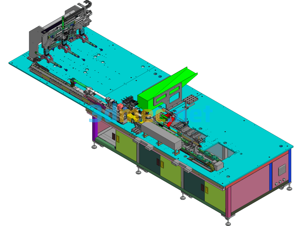
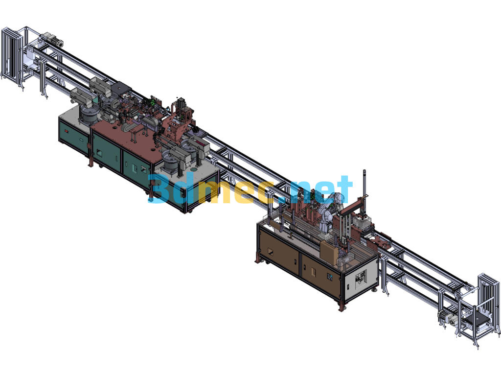
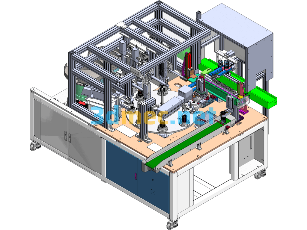
The rotor commutator of the BD1901 motor rotor commutator assembly machine includes a cylindrical insulating base, a commutator segment, and a mica sheet. The commutator is fixed on the rotor through the inner hole sleeve of the cylindrical insulating base. The commutator segment is installed in the annular mounting groove on the outer peripheral surface of the insulating base along the circumferential direction. The mica sheet is installed between adjacent commutator segments to play an insulating role. During operation, the rotor commutator rotates with the rotor. As the commutator rotates, the connection relationship between the commutator segments corresponding to each winding and the fixed brush is changed, thereby changing the current direction of each winding to ensure the magnetic force direction of the magnetic field generated by the rotor winding. The annular mounting groove of the existing commutator insulating base usually adopts a dovetail groove, and the bottom of the commutator segment is a dovetail. The axial bidirectional limit fixation and radial bidirectional limit fixation of the commutator segment are achieved through the cooperation of the dovetail and the dovetail groove; the mica sheet realizes its axial bidirectional limit fixation and radial inward limit fixation through the insulating base, and the radial outward limit fixation is achieved through the cooperation of the two adjacent commutator segments through the inclined surface. In order to facilitate the installation of the commutator segments, an opening is usually set on the side wall of the dovetail groove of the insulating base. During assembly, the commutator segments and mica sheets are inserted into the dovetail groove axially through the opening, and then slide into place circumferentially in the dovetail groove. Finally, a block is used to close the opening to complete the assembly of the commutator. However, for the rotor commutator of high-speed motors such as automobile starter motors, due to the high speed, generally more than 20,000 rpm, the dovetail groove structure is used to install the commutator segments, which is easy to cause commutator flying pieces during high-speed rotation. This equipment has been used in well-known companies such as Bosch and Dongcheng, which has improved production efficiency and won unanimous praise from customers. The drawings are editable and widely used in the industry.
Specification: BD1901 Motor Rotor Commutator Assembly Machine – 3D Model SolidWorks
|
User Reviews
Be the first to review “BD1901 Motor Rotor Commutator Assembly Machine – 3D Model SolidWorks”
You must be logged in to post a review.



There are no reviews yet.