Automatic Pressurized Impeller Assembly And Press-Fit Assembly Line (With DFM + Timing Diagram) SolidWorks 3D Model
 SolidWorks 3D Model Free Download")
 SolidWorks 3D Model Free Download")
 SolidWorks 3D Model Free Download")
 SolidWorks 3D Model Free Download")
 SolidWorks 3D Model Free Download")
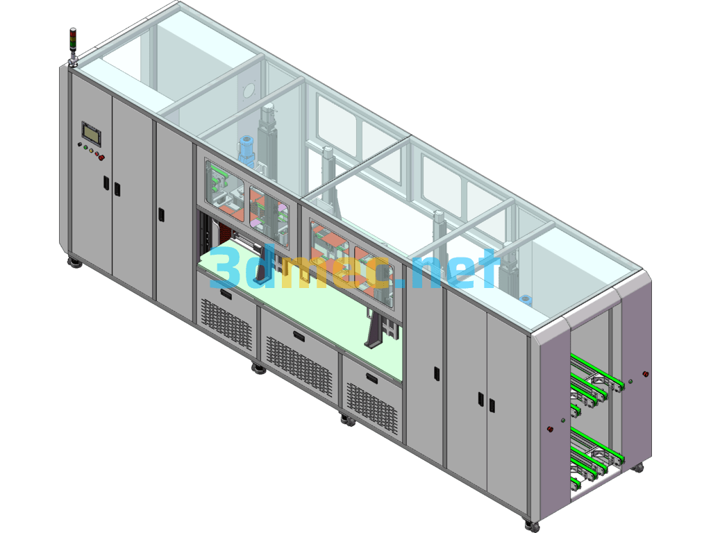
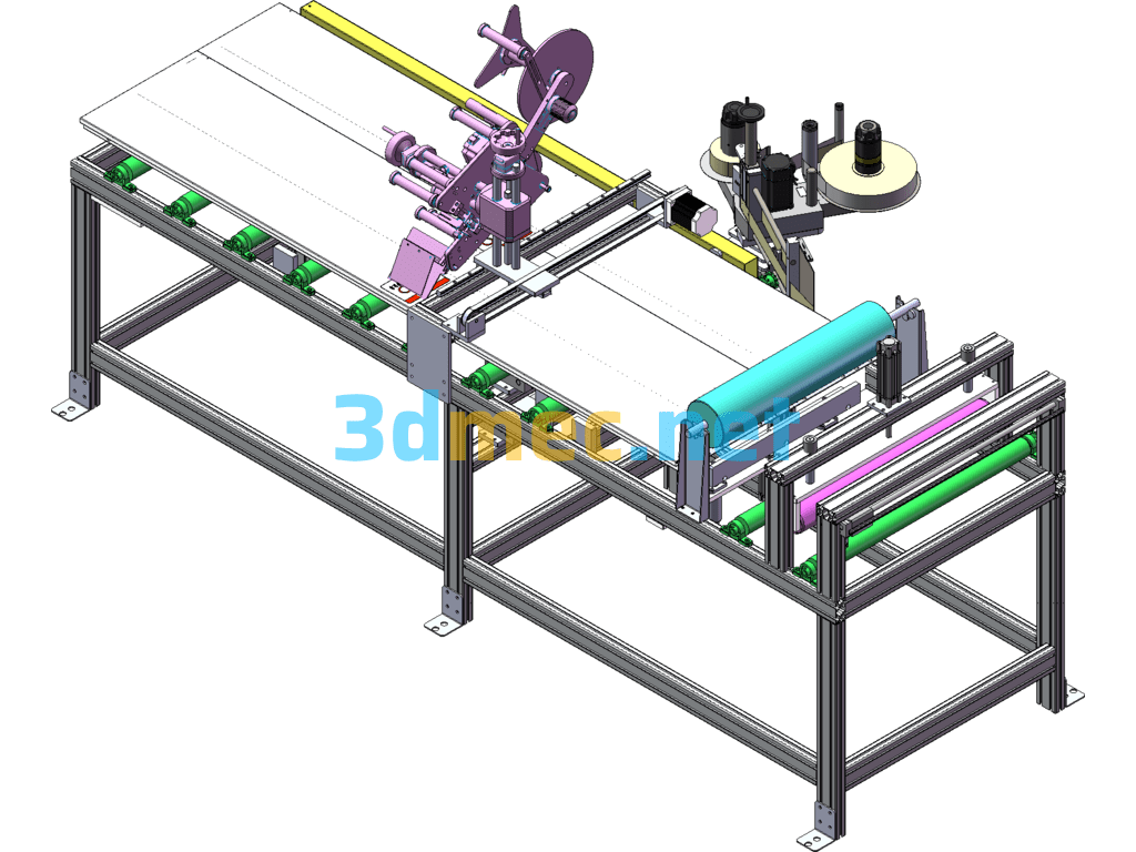
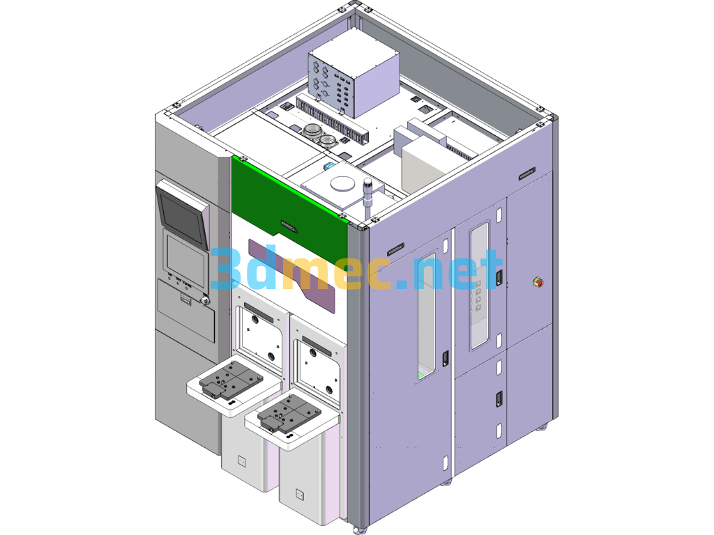
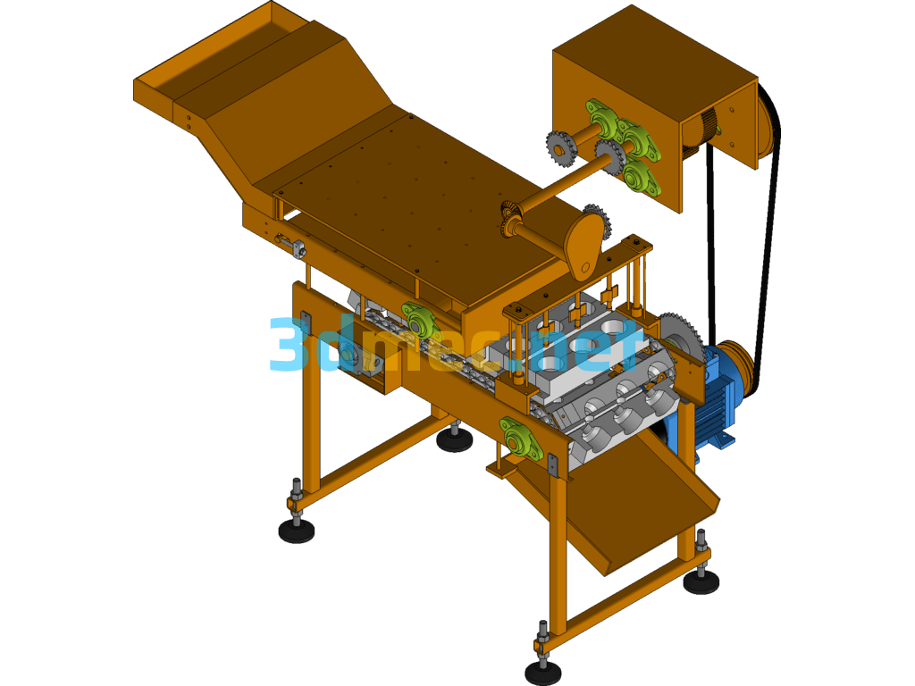
Non-standard automated booster impeller assembly press-fit line body with timing analysis diagram Description n I. This production line adopts several assembly special machines + multiple types of conveyor line combination, so as to realize the whole line automation; n The execution unit of each component adopts famous brands at home and abroad, so as to ensure the stability and service life of the equipment. n II. Equipment performance: beat: about 38s/1PCS n III. Equipment shape parameters and the number of operators required: n1. The length of the line body is 9 meters, the width is 4.5 meters, and the working height is 0.9 meters. n2. The line body requires a total of 1 person to operate the feed, upper discharge tray and NG discharge:
Specification: Automatic Pressurized Impeller Assembly And Press-Fit Assembly Line (With DFM + Timing Diagram) SolidWorks 3D Model
|
User Reviews
Be the first to review “Automatic Pressurized Impeller Assembly And Press-Fit Assembly Line (With DFM + Timing Diagram) SolidWorks 3D Model”
You must be logged in to post a review.


There are no reviews yet.