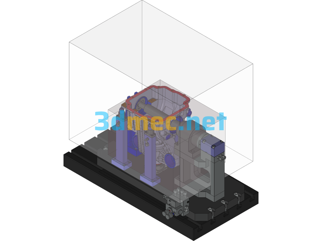
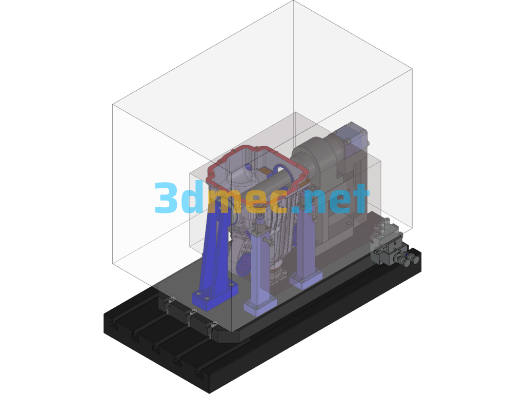
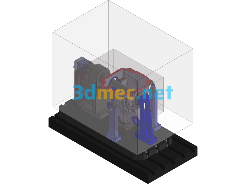
A Rear Shell Reduction Fixture (First Order) – 3D Model Exported
First sequence: Use equipment VMC850 with X stroke 800, Y stroke 450, and maximum distance from spindle nose to worktable 700
Processing parts:
1. Red mounting joint surface, and threaded hole 12-M10 on the surface, tap 27, deep 30;
2. E reference, and threaded hole 4-M15×1.5 on the surface, tap 35, deep 40;
3. FF end face, surface hole 2-φ8 hole (fine reaming) – process hole of the part;
Clamping principle:
Use C and D reference rough blank for centering (long mandrel principle) to limit four degrees of freedom; C reference end face is used for axial limit; A reference end face is used for angular positioning; the rest are added with auxiliary support according to the clamping situation;
Specification: A Rear Shell Reduction Fixture (First Order) – 3D Model Exported
|
User Reviews
Be the first to review “A Rear Shell Reduction Fixture (First Order) – 3D Model Exported”
You must be logged in to post a review.




There are no reviews yet.