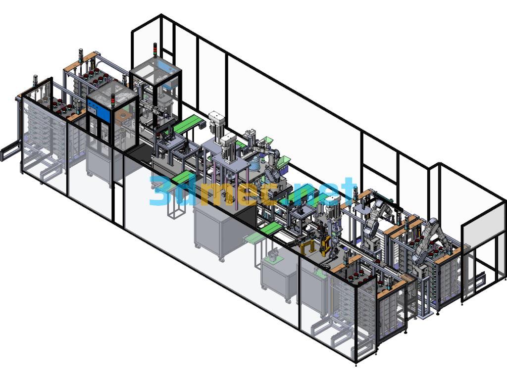
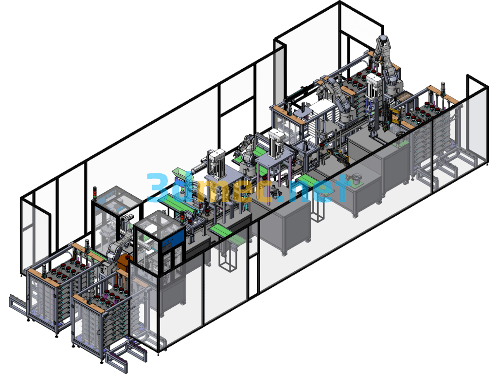
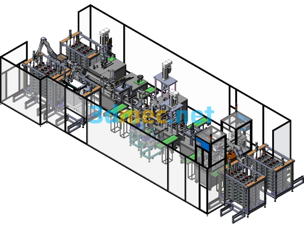
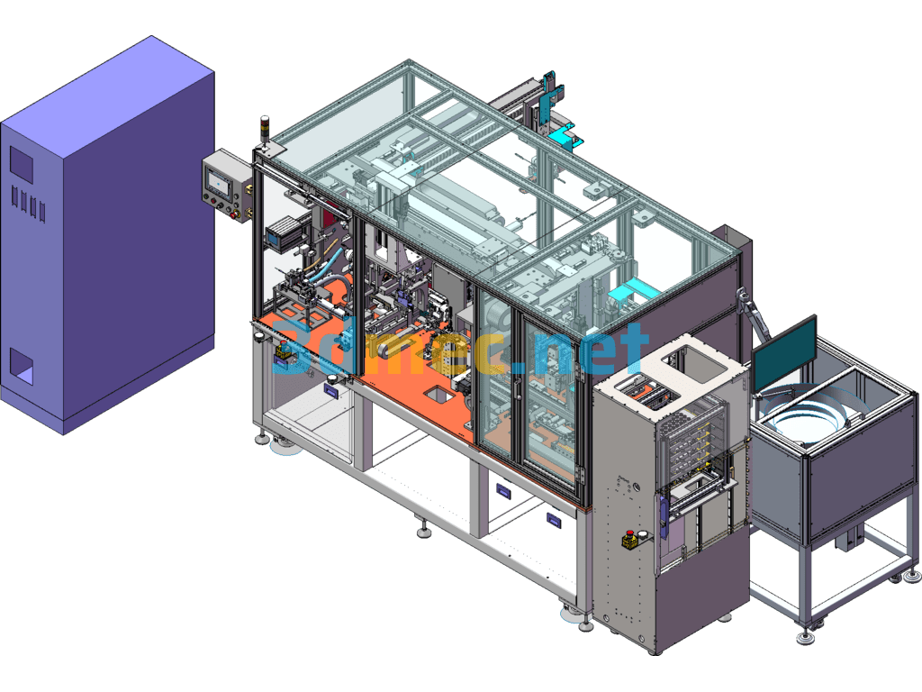
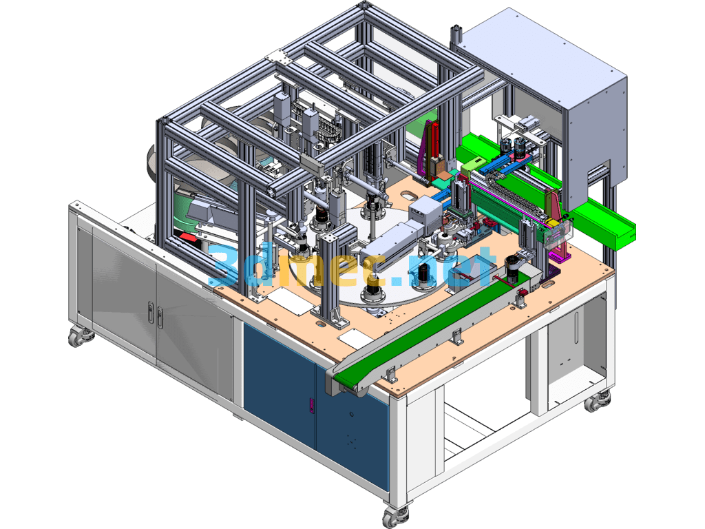
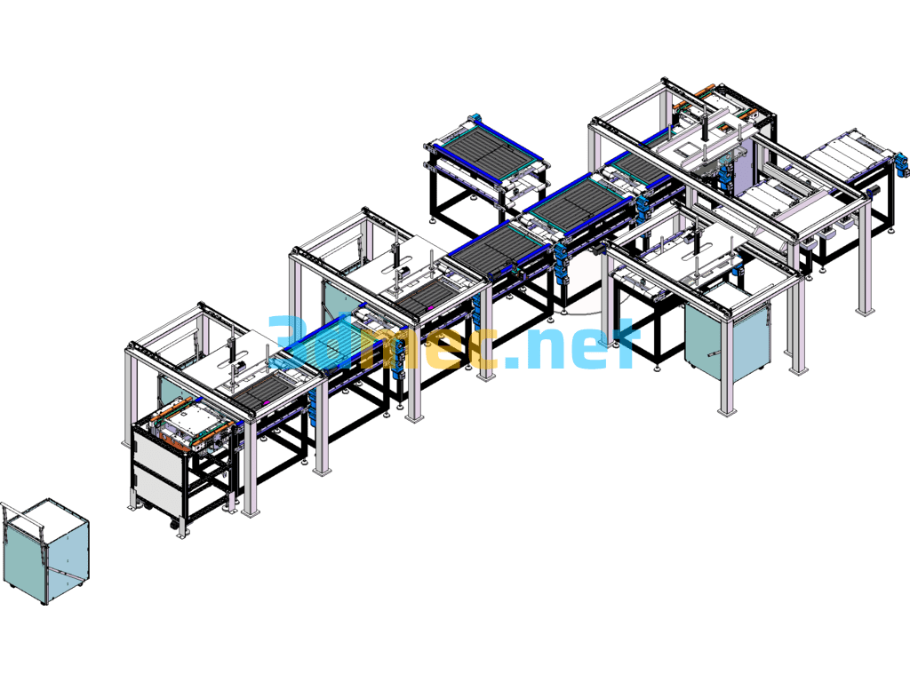
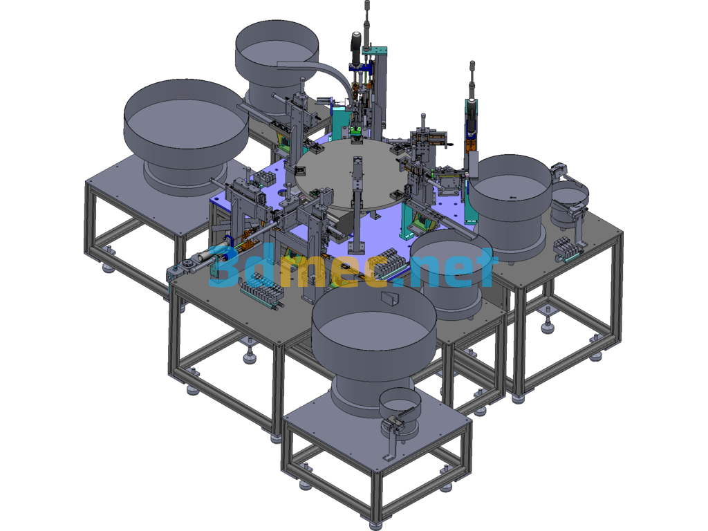
Non-standard automatic booster impeller assembly and pressing line with timing analysis diagram
1. This production line is composed of multiple assembly machines + various types of conveying lines, thus realizing full line automation;
All its components and execution units are well-known domestic and foreign brands, thus ensuring the stability and service life of the equipment;
2. Equipment performance: Beat: about 38s/1PCS
3. Equipment appearance parameters and required number of operators:
1. The line length is 9 meters, the width is 4.5 meters, and the operating height is 0.9 meters
2. The line requires a total of 1 person to operate the feeding, unloading tray, and NG unloading:
Specification: Automatic Booster Impeller Assembly And Pressing Line (Including DFM+ Timing Diagram) – 3D Model SolidWorks
|
User Reviews
Be the first to review “Automatic Booster Impeller Assembly And Pressing Line (Including DFM+ Timing Diagram) – 3D Model SolidWorks”
You must be logged in to post a review.




There are no reviews yet.