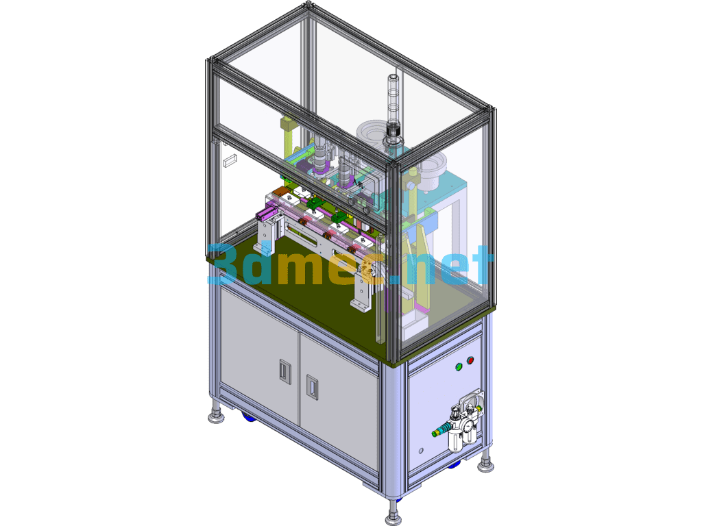
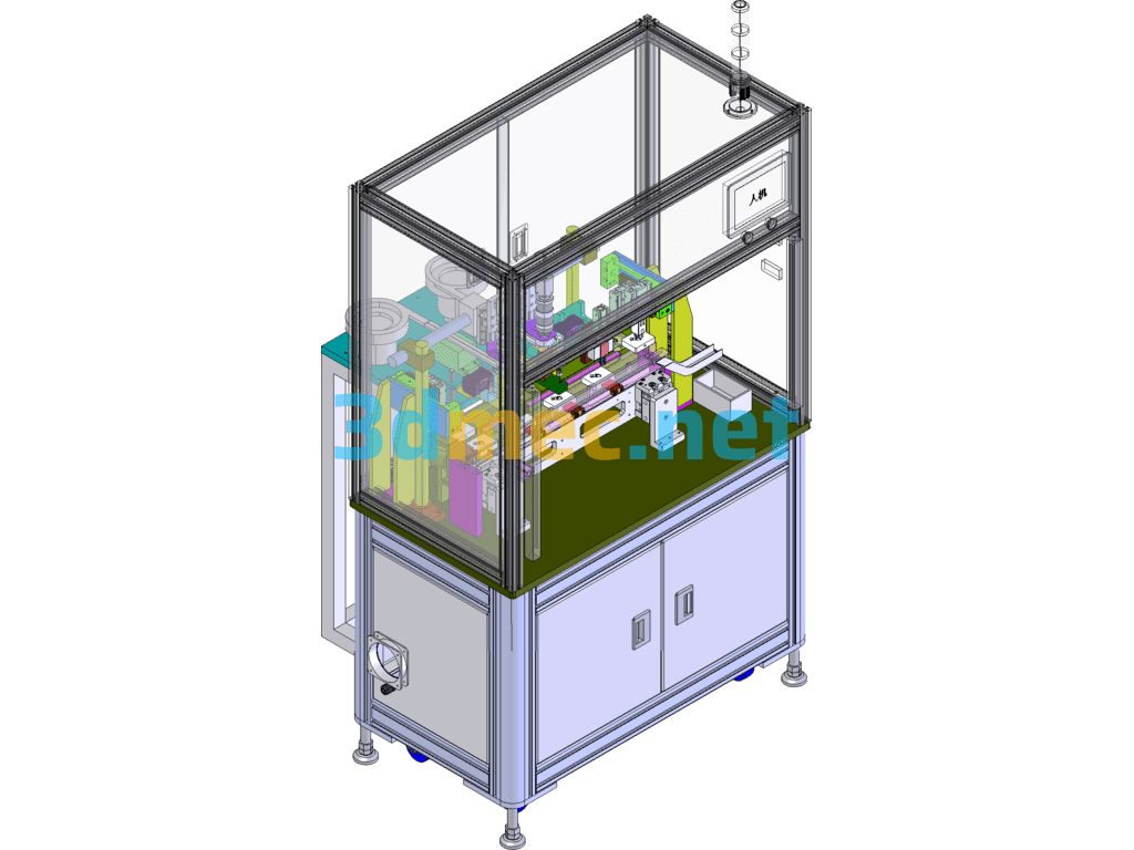
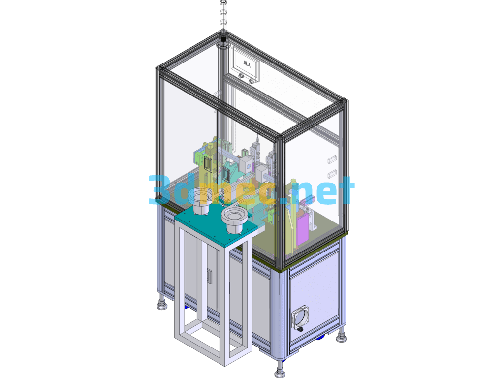
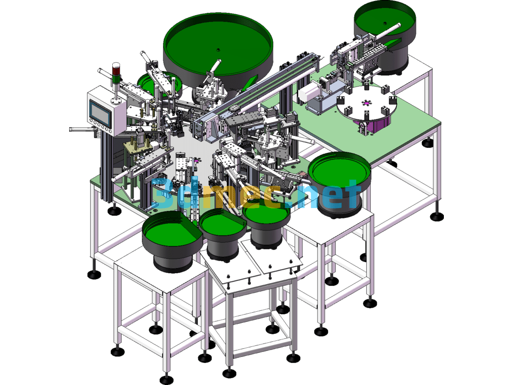
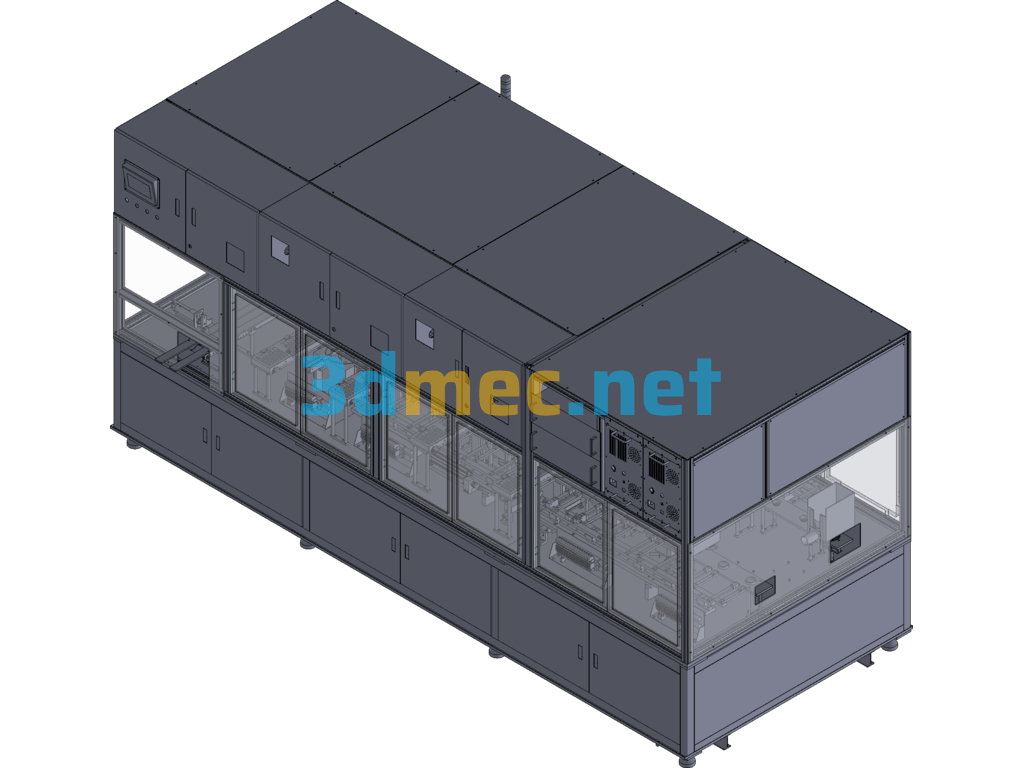
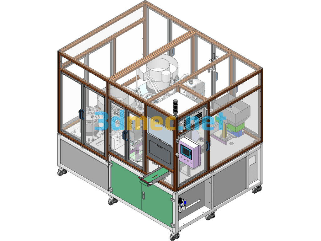
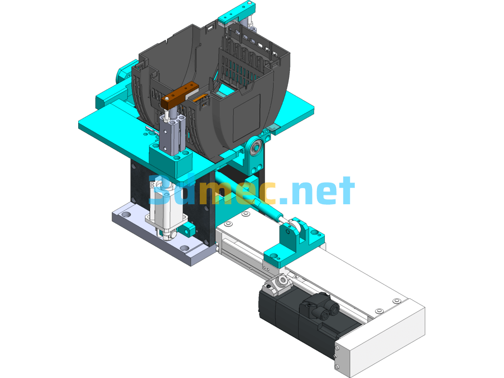
Description of the operation of the automatic PIN assembly and lamination detection equipment:
The first step: manually put the materials into the carrier respectively;
The second step: vibrating plate feeding;
The third step: Material CCD alignment;
Step 4: Cylinder feeding
Step 5: Carrier positioning
Step 6: Short needle & long needle and pressing in place simultaneously.
). Step 7: Moving the vehicle
Step 8: Picking up the object with the gripper
Step 9: Manually recovering the finished product
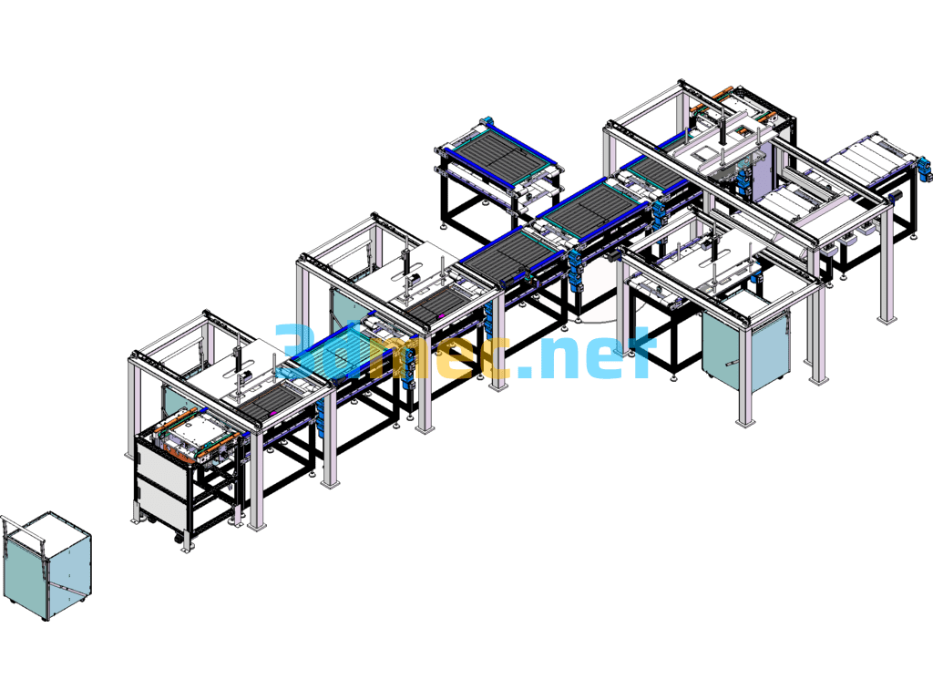
Specification: Automatic PIN Assembly Press Tester (Including DFM, Timing Diagram) – 3D Model SolidWorks
|
User Reviews
Be the first to review “Automatic PIN Assembly Press Tester (Including DFM, Timing Diagram) – 3D Model SolidWorks”
You must be logged in to post a review.




There are no reviews yet.