A Pneumatic Plug Seedling High-Speed Transplanting Mechanical Claw – 3D Model SolidWorks
Inventions designed by myself before
[0001]The present invention belongs to the field of agricultural machinery. It designs a pneumatic high-speed transplanting mechanical claw for seedlings in a tray, which is mainly used as the end actuator of a high-speed transplanting machine for greenhouses, and is used to clamp seedlings in trays.
Technical background
[0002] In modern agricultural greenhouses, seedlings are mostly grown in trays, which can effectively improve the survival rate and economic benefits of seedlings and shorten the seedling growing time. Due to these advantages of tray seedlings, it is easy to standardize operations, can be sown by machine, and is suitable for large-scale factory seedlings, which saves labor and effort and has high efficiency. At present, all factory seedlings in my country use tray seedlings. The large-scale transplanting of tray seedlings uses traditional manual transplanting methods, which has a harsh working environment, low efficiency, and high cost. The convenience of seedling cultivation in the early stage will be covered up, which limits the development of tray seedling cultivation. Therefore, a high-speed transplanting machine for tray seedlings is needed to help the high-speed transplanting of tray seedlings in greenhouses. Using a high-speed transplanter to transplant seedlings in trays can improve the working environment and facilitate manual operation. You can sit in the lounge of the greenhouse, put the tray on the operating table, and use the machine to complete the transplanting, which is comfortable and convenient.
[0003]With the development of science and technology and the improvement of people’s living standards, the automation of facility agricultural production has become an inevitable trend in the development of modern agriculture. Among them, the automation technology of transplanting operations is one of the key technologies for the automation of facility agricultural production. The tray seedling transplanting robot is a key equipment for realizing the automatic transplanting of seedling tray seedlings. The transplanting mechanical claw is an important component of the transplanting robot that is in direct contact with the seedlings, and its working performance directly affects the quality of transplanting. Therefore, the development of a transplanting mechanical claw with stable performance and high efficiency is of great significance for improving the transplanting survival rate of the transplanting robot and the efficient operation of the transplanting machine.
[0004]The purpose of the present invention is to provide a high-speed transplanting mechanical claw driven by a cylinder and an electromagnetic push rod, with precise drive control and fast working speed, and can accurately and quickly complete the grabbing and releasing actions of the seedlings.
[0005] The purpose of the present invention is achieved through the following technical solutions: a high-speed transplanting mechanical claw, consisting of a main frame, a cylinder 1, an electromagnetic push rod 5, and a grasping mechanism; the push rod part of the cylinder 1 is fixed on the upper end fixing plate; the electromagnetic push rod 5 is fixed on the lower end fixing plate in the main frame, and the mechanical claw mounting bracket is fixed on the main frame.
[0006] The main frame is a two-layer frame structure, which is divided into an upper limit fixing plate 2, upper and lower limit plate connecting bolts 8, a lower limit fixing plate 4, bolts, nuts and other components. The upper fixed limit plate 2 is fixedly connected to the cylinder push rod 10. The upper limit fixing plate 2 and the lower limit fixing plate 4 are connected and fastened by bolts and nuts through the upper and lower limit plate connecting bolts 8. The lower limit fixing plate 4 is fixedly connected to the electromagnetic push rod 5, and is hinged to the four surrounding small cylinders 3 through the small cylinder swing connector 9.
[0007] The grabbing mechanism is composed of six parts, namely, an electromagnetic push rod 4, a small cylinder swing connector 9, a connecting rod 15 between the rod 9 and the rod 12, a small cylinder 3, a plate-shaped steel needle sleeve 7, and a plate-shaped steel needle 6.
[0008] Furthermore, the electromagnetic push rod 5 is hinged with the connecting rod 15 between the rod 9 and the rod 12, and the small cylinder swing connector 9 is fixed to the small cylinder 3, thereby driving the small cylinder 3 to swing around the frame and driving the plate-shaped steel needle 6 to move. The plate-shaped steel needle sleeve 7 is sleeved on the plate-shaped steel needle 6 to facilitate the detachment of the plate-shaped steel needle 6 when the transplanting of the transplanted seedlings is completed.
[0010] The present invention has the beneficial effects that the transplanting mechanical claw of the present invention has a small overall volume and can grasp accurately and quickly. The cylinder 1 can accurately and quickly output the distance, thereby accurately and quickly driving the frame to reach the specified position and improving the working speed. The electromagnetic push rod 5 controls the clamping action, and can control the force of the plate-shaped steel needle 6 on the transplanted object, better protect the transplanted object, and is more conducive to high-speed transplanting. At the same time, the opening size of the plate-shaped steel needle 6 can be controlled by a signal, so that the mechanical claw can be applied to different types of seedling trays.
Description of the accompanying drawings
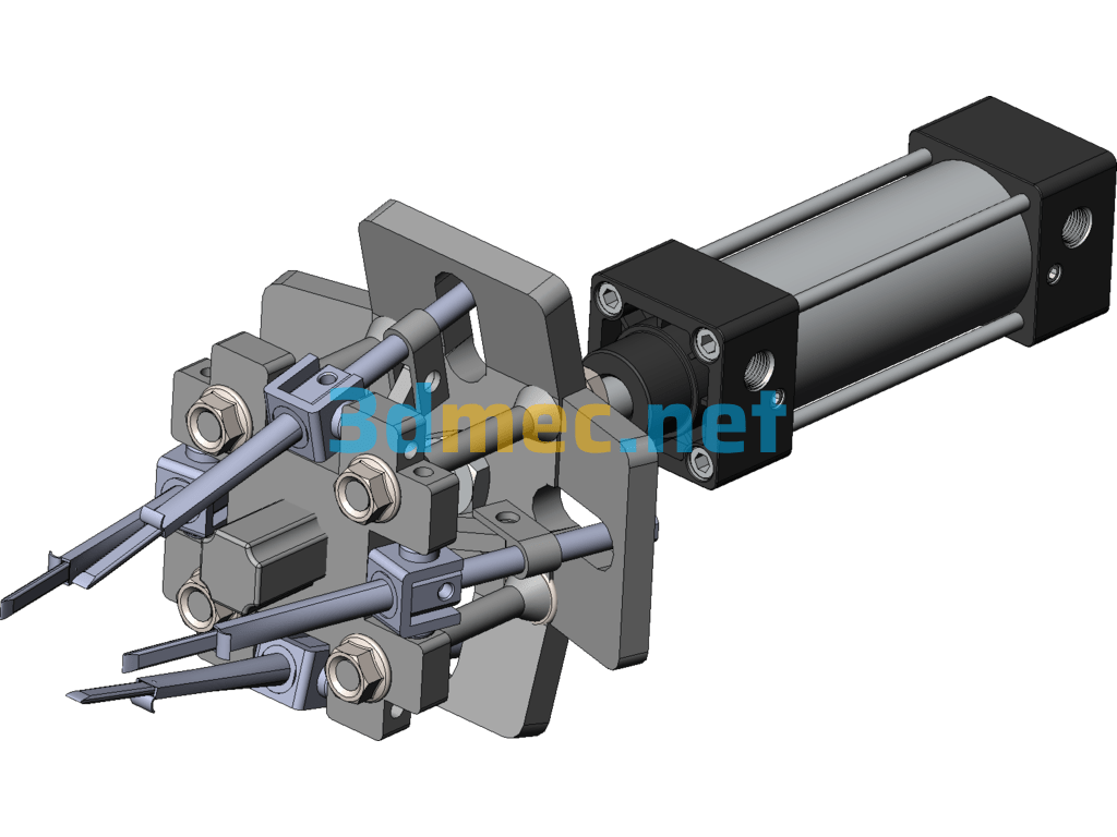
[0011] Figure 1 is a front view of the mechanical claw
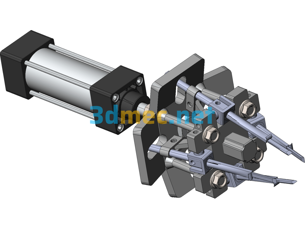
[0012] Figure 2 is a partial view of the mechanical claw
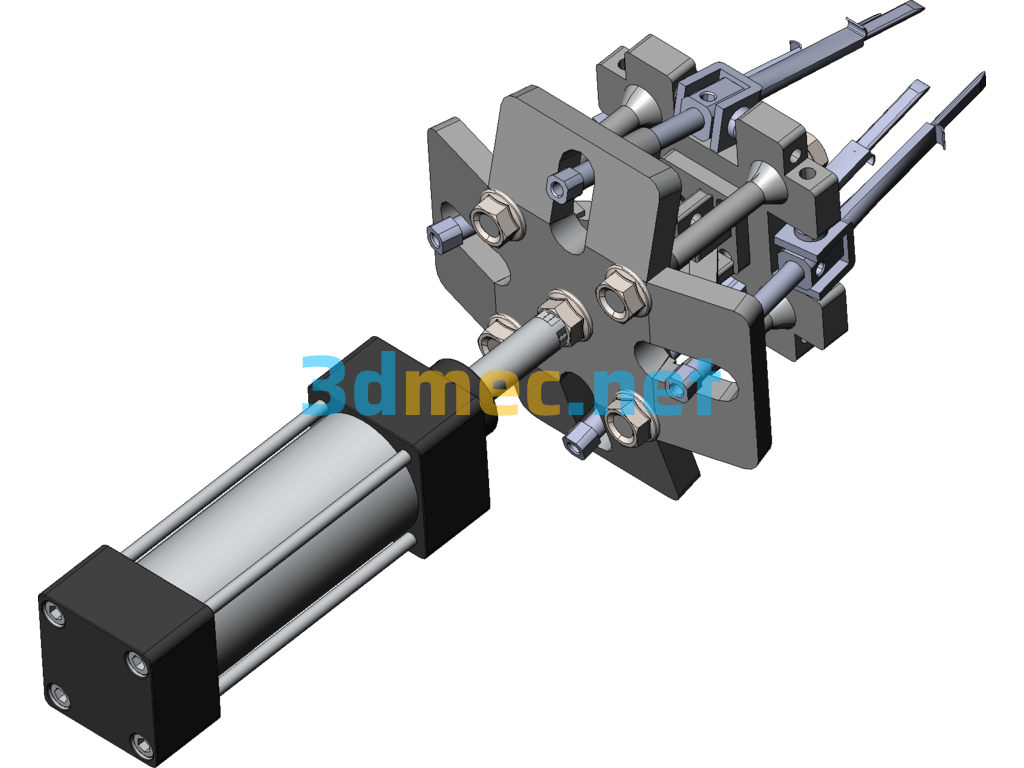
[0013] Figure 3 is an axonometric view of the mechanical claw
[0014] Figure 4 is a bottom view of the mechanical claw
[0015] In the figure, cylinder 1, upper fixed limit plate 2, small cylinder 3, lower limit fixed plate 4, electromagnetic push rod 5, plate-shaped steel needle 6, plate-shaped steel needle sleeve 7, upper and lower limit plate connecting bolts 8, small cylinder swing connecting piece 9, cylinder push rod 10, electromagnetic push rod top connecting piece 12, small cylinder and lower limit plate U-shaped connecting piece 14, connecting rod 15 between rod 9 and rod 12, and several pin connecting pieces.
Specific implementation method
[0016]The mechanical claw is further described in detail below in conjunction with the accompanying drawings.
[0017]As shown in Figures 1 and 3, the present invention is composed of a main cylinder 1, an upper fixed limit plate 2, a small cylinder 3, a lower limit fixed plate 4, an electromagnetic push rod 5, a plate-shaped steel needle 6, a plate-shaped steel needle sleeve 7, upper and lower limit plate connecting bolts 8, a small cylinder swing connector 9, a cylinder push rod 10, an electromagnetic push rod top connector 12, a small cylinder and a lower limit plate U-shaped connector 14, a connecting rod 15 between the rod 9 and the rod 12, and a pin connector; the cylinder The cylinder push rod 10 is connected to the upper fixed limit plate 2 through a threaded nut and is located at the top. The upper and lower fixed limit plates 2 and 4 are connected through four connecting bolts 8 and are located in the middle. The swing connector 9 and the connector 15 are respectively fixedly connected to the small cylinder 3. At the same time, the four small cylinders are in the limit groove of the upper limit plate 2. The electromagnetic push rod 5 is located in the middle of the bottom surface of the lower limit plate 4. The plate-shaped steel needle 6 is located in the plate-shaped steel needle sleeve 7. The steel needle 6 is connected to the telescopic push rod of the small cylinder.
[0018] The small cylinder 3, the small cylinder swing connector 9, the electromagnetic push rod top connector 12 and the connecting rod 15 constitute a hinge swing rod mechanism. The swing of the small cylinder 3 is achieved by the drive of the electromagnetic push rod 5, and then the angle swing of the mechanism plate-shaped steel needle 6 is achieved, which is convenient for inserting the soil at a suitable angle to grab the seedlings in the hole tray.
[0019]The small cylinder 3 and the lower limit fixing plate 4 are hinged through the U-shaped connecting piece 14 between the small cylinder and the lower limit plate, so that the small cylinder can swing around the axis.
The bottom of the plate-shaped steel needle sleeve 7 has an outward bending plate 11, which presses the transplanted seedlings when the transplanted plate-shaped steel needles 6 are retracted to prevent the transplanted seedlings from being taken out of the hole tray due to the retraction of the plate-shaped steel needles 6.
[0020]As shown in the figure, the four plate-shaped steel needles 6 are cross-distributed. When transplanting and taking seedlings, due to the action of the limit slots of the upper fixed limit plate 2 and the lower limit fixing plate 4, the angle of inserting the seedlings into the hole is about 15 degrees, making it easy to take the seedlings.
[0021]The working process of the present invention is as follows
[0022]When the mechanical transplanting claw is working, it is located above the seedlings in the hole tray to be transplanted, and the transplanting claw is brought to a suitable height by the action of the cylinder 1; in this process, the control signal controls the electromagnetic driving rod 5 to work, so that the mechanical transplanting claw opens to prevent the mechanical claw from damaging the seedlings in the hole tray during the descent process; after reaching the specified position, the electromagnetic driving rod 5 contracts to close the mechanical claw, and because of the limiting action of the upper and lower limit plates, the plate-shaped steel needle 6 is aligned with the soil matrix of the seedlings in the hole tray to be transplanted at a suitable angle; then four small cylinders 3 act at the same time to push the four plate-shaped steel needles into the soil, and with the action of the cylinder 1, the plate-shaped steel needles are retracted upward to take the seedlings out of the hole tray; when the transplanting claw moves to the transplanting position, the cylinder 1 extends downward again to place the transplanted seedlings into the soil matrix to be transplanted; then the four small cylinders 3 act to retract the plate-shaped steel needle 6, and after the retraction, the cylinder 1 begins to contract, raising the mechanical claw, completing the transplanting process, and starting the next round of transplanting process.
Specification: A Pneumatic Plug Seedling High-Speed Transplanting Mechanical Claw – 3D Model SolidWorks
|
User Reviews
Be the first to review “A Pneumatic Plug Seedling High-Speed Transplanting Mechanical Claw – 3D Model SolidWorks”
You must be logged in to post a review.



There are no reviews yet.