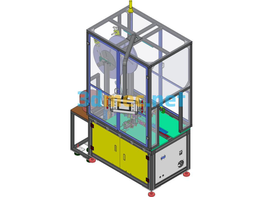
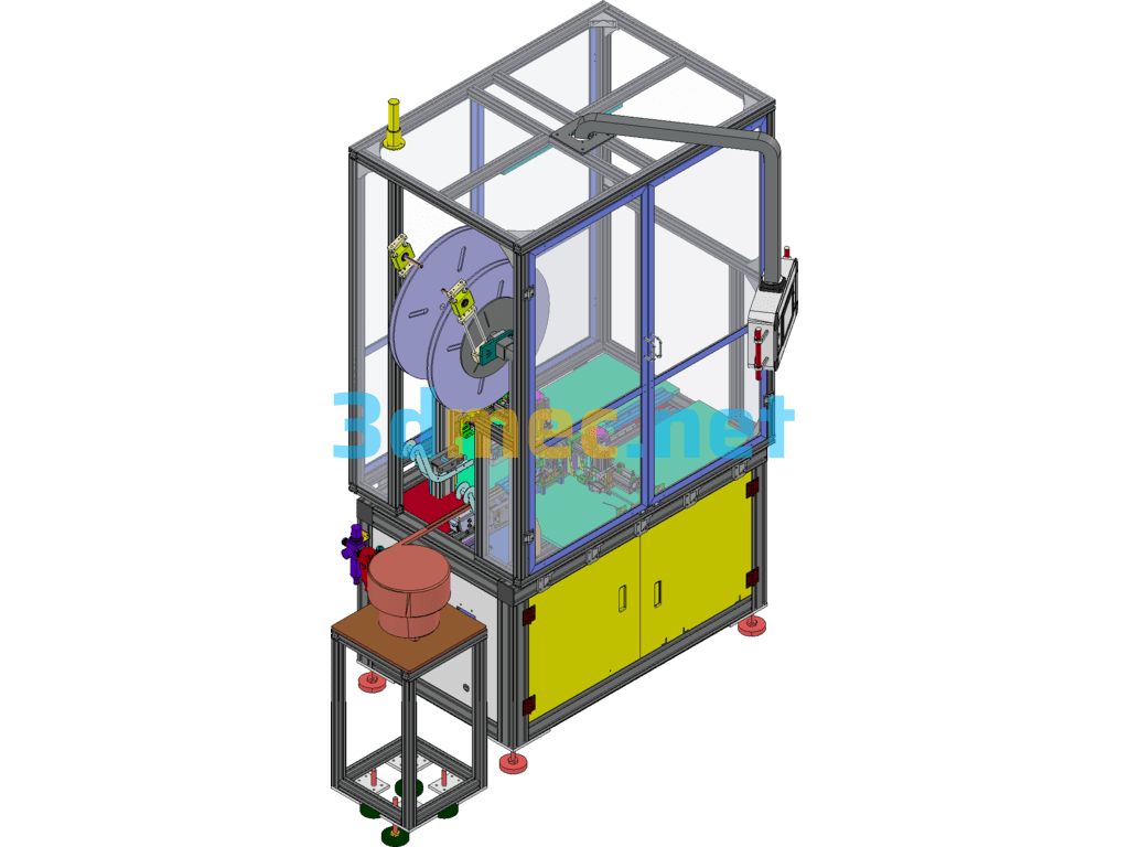
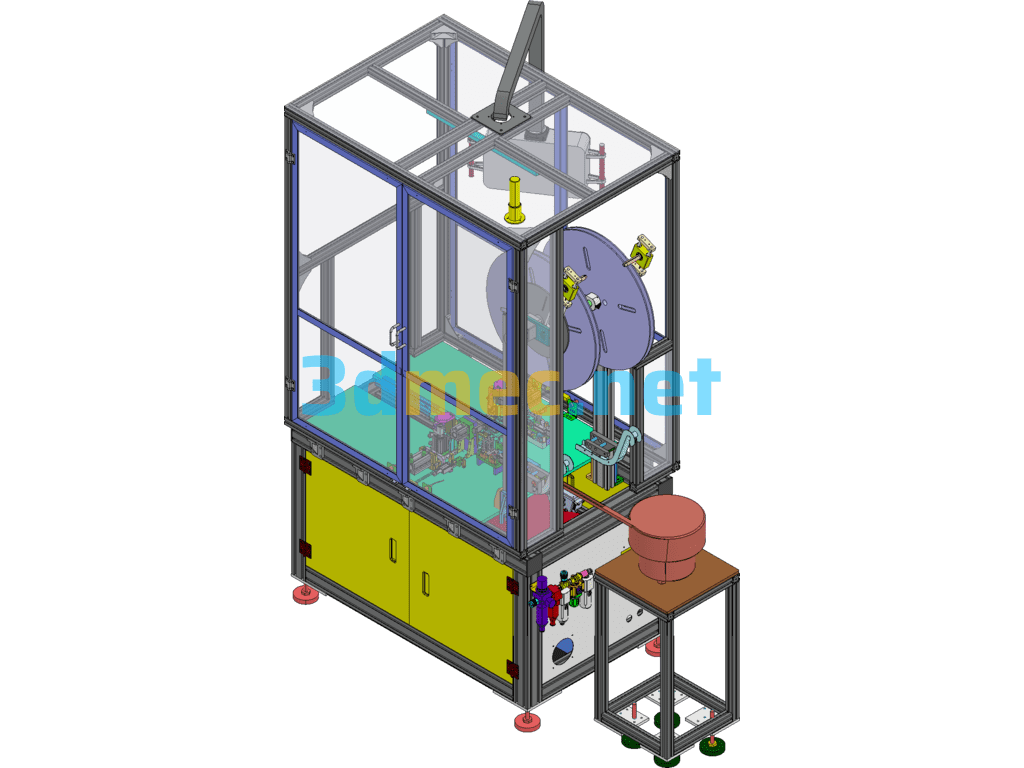
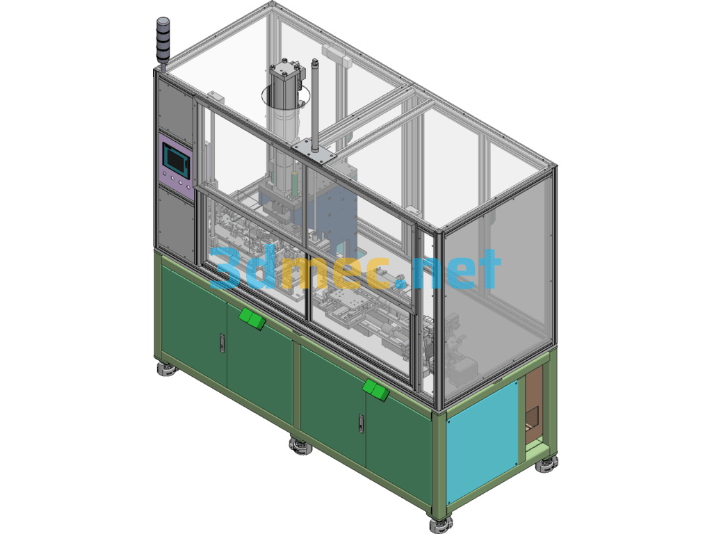
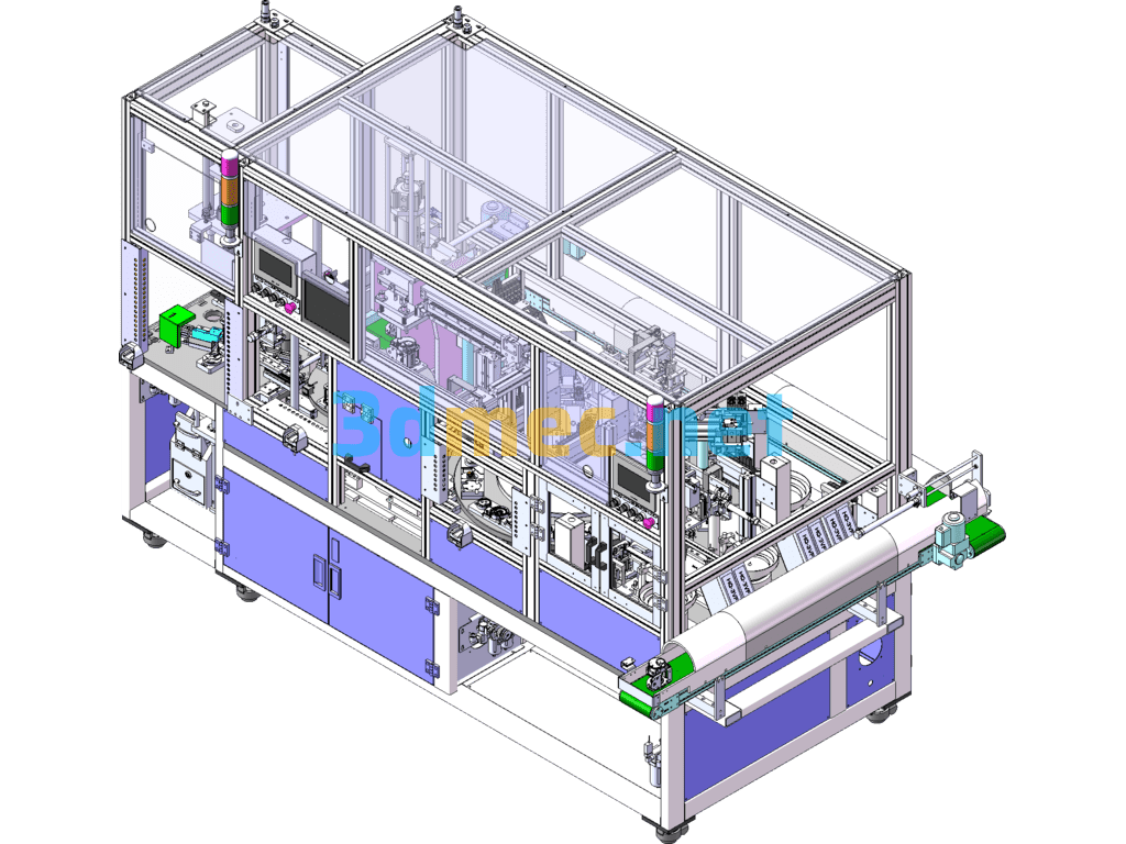
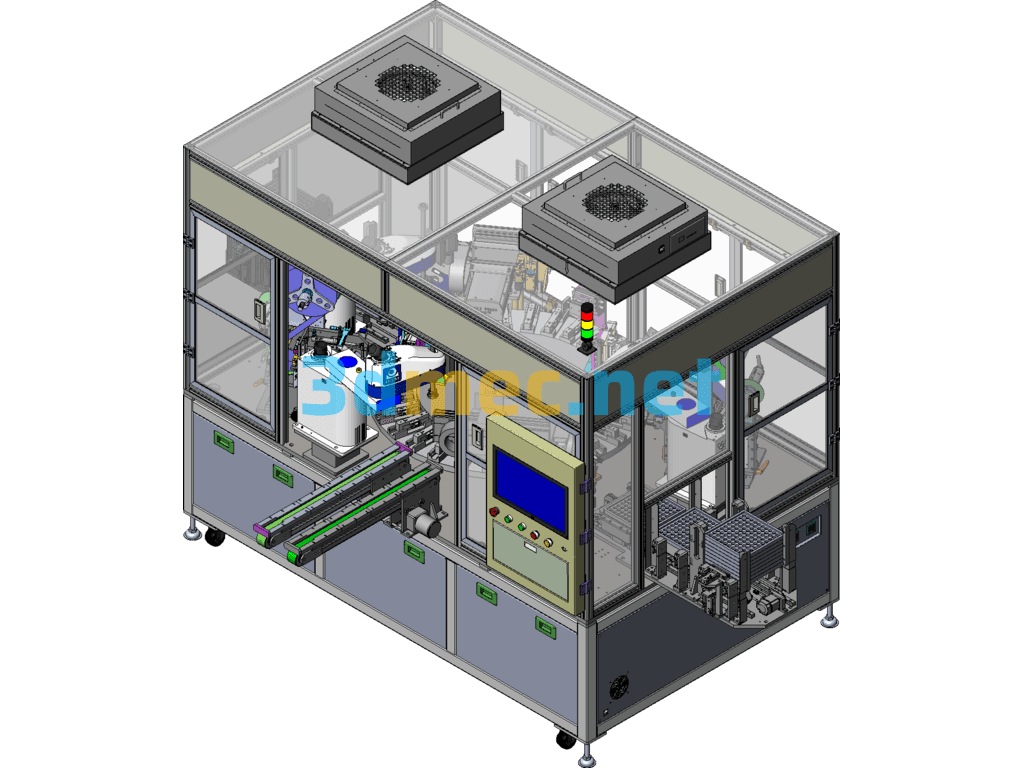
Brief introduction to the operation process of the automatic cutting and PIN installation machine:
1. PINs are fed into the equipment by two sets of flying discs, and the materials are fed in automatic sections;
2. The plug-in is fed by a vibration plate, and the product is sent into the equipment and positioned by direct vibration.
3. After the PIN enters the equipment, the cylinder module completes the cutting, moves to the lower station, and the PIN is directly pressed into the plug-in to complete the assembly.
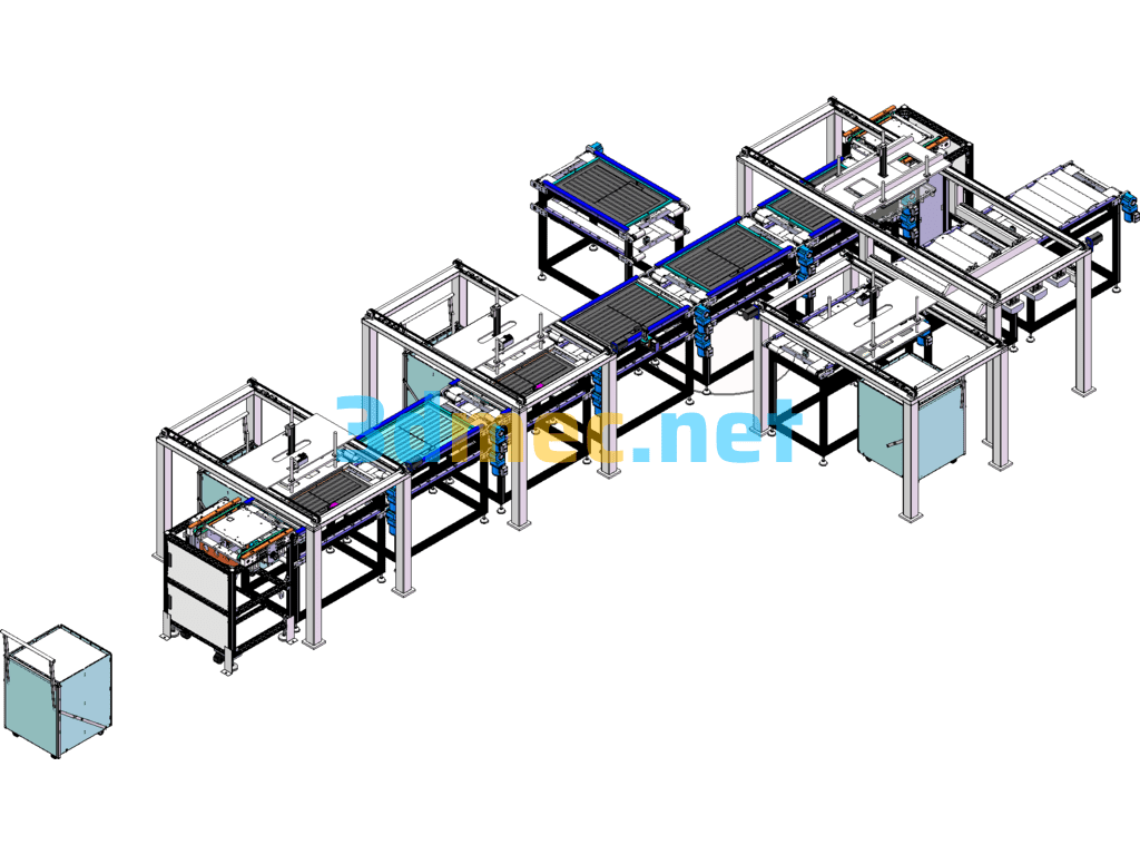
Specification: Automatic Cutting And PIN Installation Equipment (Including DFM, BOM) – 3D Model SolidWorks
|
User Reviews
Be the first to review “Automatic Cutting And PIN Installation Equipment (Including DFM, BOM) – 3D Model SolidWorks”
You must be logged in to post a review.


There are no reviews yet.