I. Performance and Features:
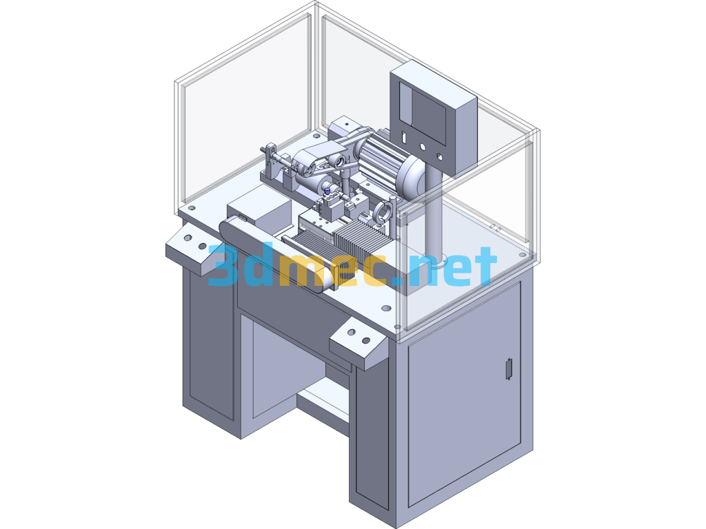
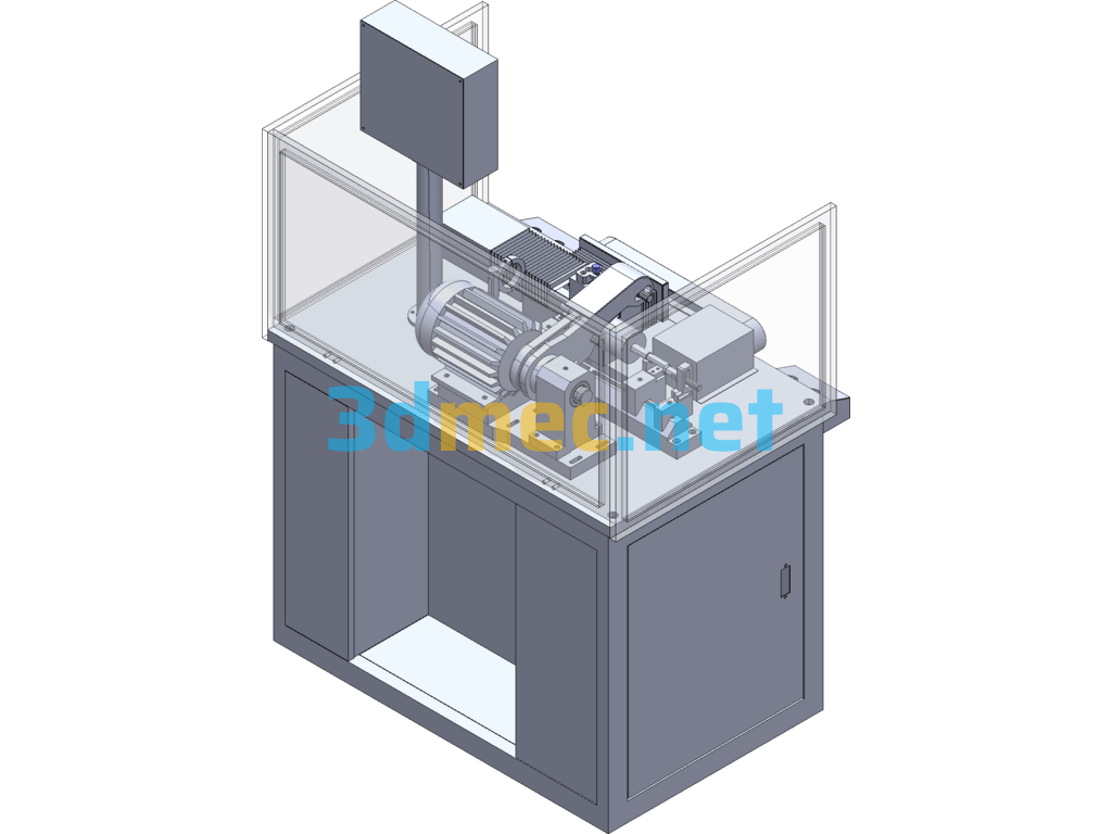
1. This machine is suitable for precision turning of the outer circle of the commutator or rotor core.
2. X and Y axes use imported brand (THK) precision rolling screw guide rail transmission.
3. The grinding grade diamond V-shaped frame is durable and has stable precision.
4. It adopts Japanese PLC for program control, equipped with touch screen, and has high system reliability.
5. X and Y axes use Japanese servo system, with stable turning accuracy and quality, and can pass the tool multiple times.
6. Optional chip sweeping device and dust suction device.
II. Technical parameters:
1. Turning part: outer circle of rotor commutator;
2. Diameter of rotor core: ≤Φ80mm;
3. Length of rotor core shaft: ≤270mm;
4. Diameter of rotor core shaft: Φ1.5~Φ15mm;
5. Diameter of commutator outer circle: Φ4~Φ40mm;
6. Maximum processing length: ≤25mm;
7. Radial runout of processed commutator: ≤0.005mm;
8. Axial runout of processed commutator: ≤0.005mm;
9. Production efficiency: 10 seconds/piece (turning 2 times);
10. Input power: 3KW;
11. Air source pressure: 0.5~0.8MPa;
12. Machine size: 900x700x1480mm;
13. Weight: 350kg;
14. Special customization available
Specification: Single-Blade Dual-Servo Precision Turning Machine Type Ⅰ 3D+ Engineering Drawing – 3D Model SolidWorks
|
User Reviews
Be the first to review “Single-Blade Dual-Servo Precision Turning Machine Type Ⅰ 3D+ Engineering Drawing – 3D Model SolidWorks”
You must be logged in to post a review.




There are no reviews yet.