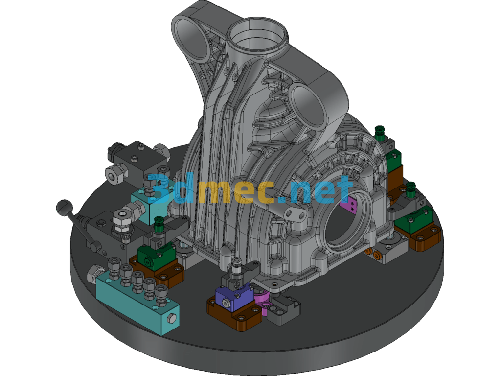
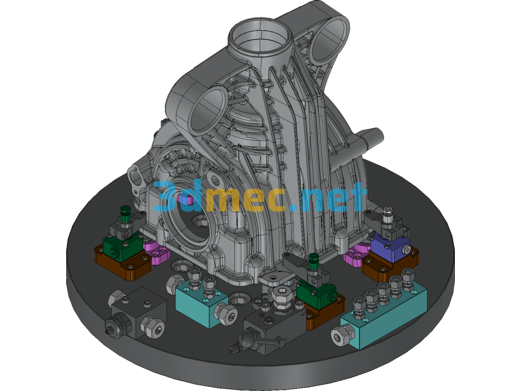
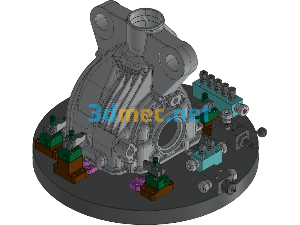
The third sequence: Equipment used: CNC vertical lathe
Processing parts: A, B reference holes and end faces;
Clamping principle:
Use the mounting surface processed in the first sequence as the installation surface, and the two 2-φ8 pin holes in the FF view for centering, with two pins on one side;
Specification: A Rear Shell Reduction Fixture (Third Order) – 3D Model Exported
|
User Reviews
Be the first to review “A Rear Shell Reduction Fixture (Third Order) – 3D Model Exported”
You must be logged in to post a review.



There are no reviews yet.