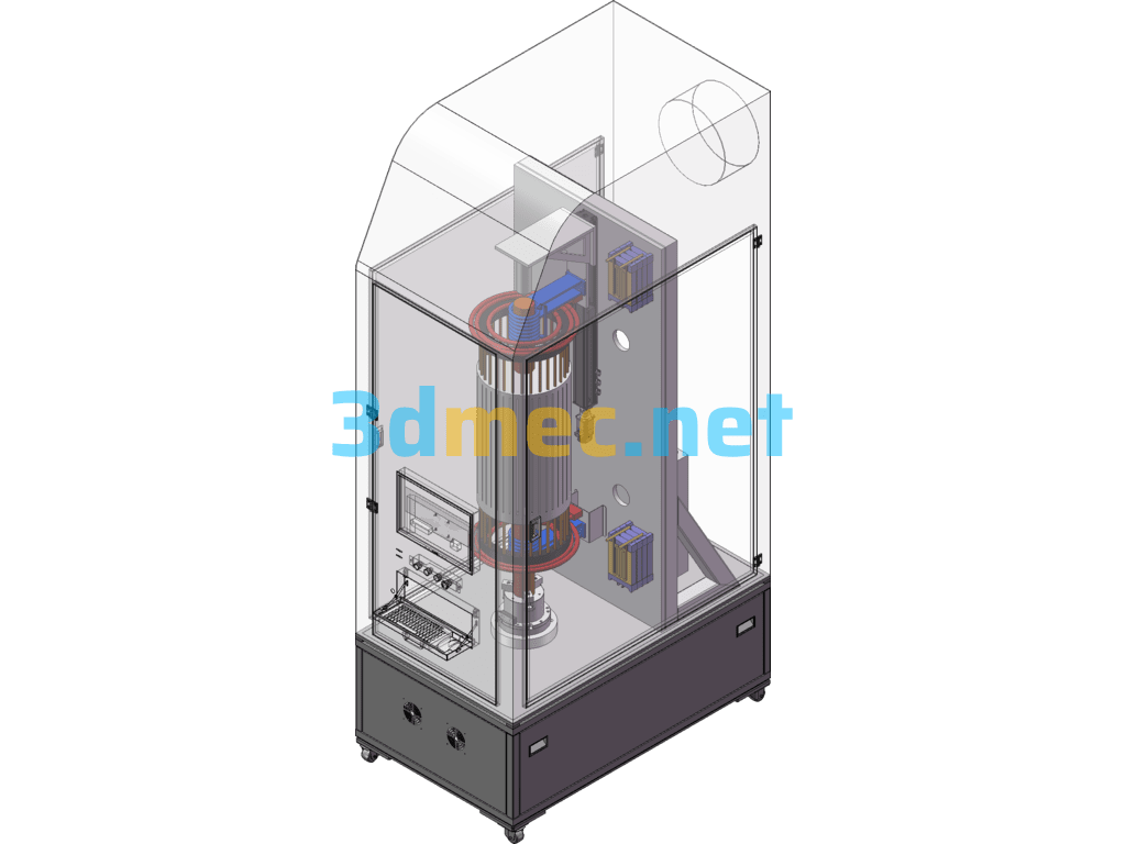
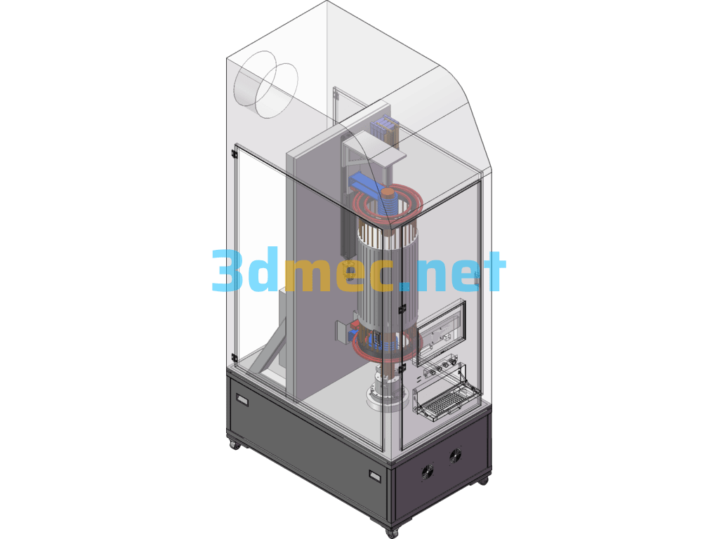
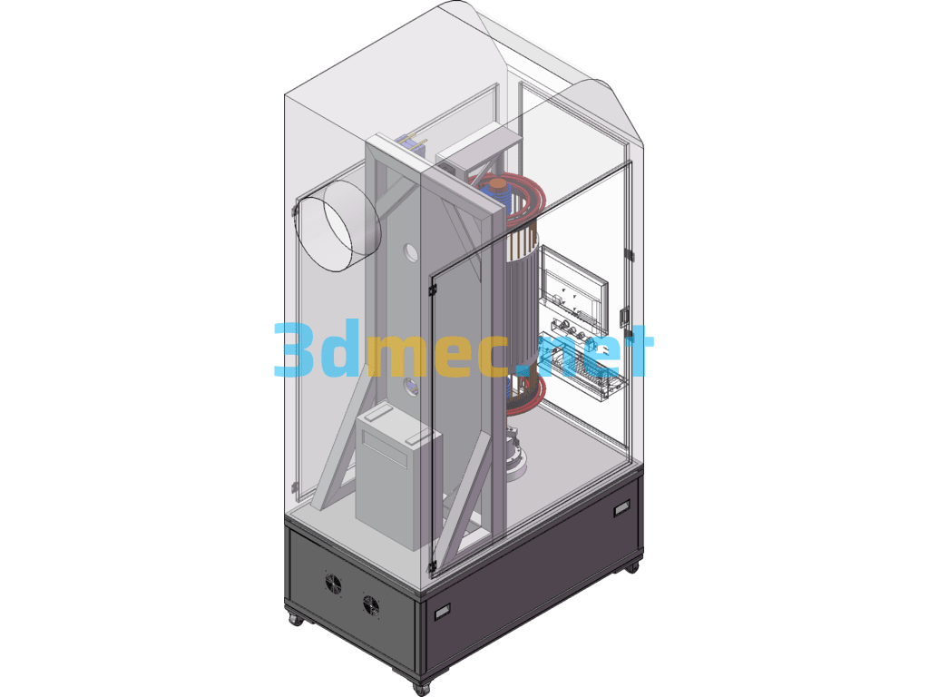
(Reprinting is strictly prohibited) The main purpose is that the motor drives the three-jaw chuck to rotate at a uniform speed, and then a heating ring heats the clamped rotor for welding. The working principle is as follows:
Clamp one end of the rotor ready for welding the copper end ring on the three-jaw chuck, and fix the other end with a floating center. After fixing, evenly apply the brazing material to the copper end rings on both sides, and start the motor after evenly applying it. The motor drives the V-belt transmission, and the V-belt connects the bevel gear to rotate in reverse, and the bevel gear drives the three-jaw chuck to rotate at a uniform speed. After starting the motor, start the induction heating rings on both sides of the copper end ring to heat up, and at the same time start the water cooling circulation ring in the induction ring to protect the finished rotor shaft from being deformed by heat again. The copper end ring is evenly heated when the three-jaw chuck rotates, until the entire copper end ring is brazed, the heating device is turned off, and then the motor is turned off, and the water cooling circulation ring is turned off after the temperature of the welding part drops
In addition, in terms of structural layout, the motor is placed horizontally, the belt drive is connected to the bevel gear, and the bevel gear is reversed to connect the three-jaw chuck to rotate horizontally. The workpiece is clamped vertically by a three-jaw chuck, and the upper part is fixed by a center (reproduction is strictly prohibited)
Specification: Squirrel Cage Rotor Copper End Ring Welding Device – 3D Model SolidWorks
|
User Reviews
Be the first to review “Squirrel Cage Rotor Copper End Ring Welding Device – 3D Model SolidWorks”
You must be logged in to post a review.




There are no reviews yet.