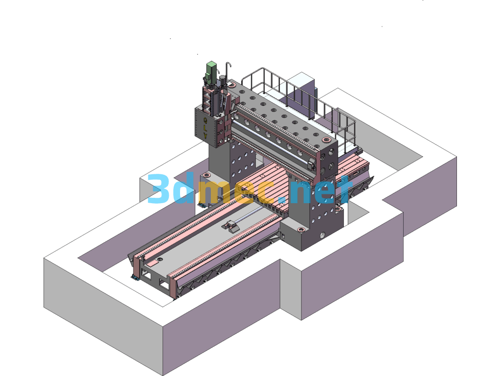
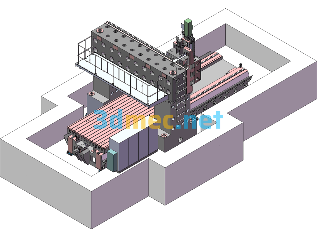
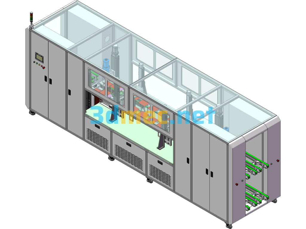
The overall layout of the 2540 gantry milling machine adopts a high-rigidity structure. The work table and guide rail surfaces are precision ground to ensure good accuracy. The Z-axis adopts a reinforced spindle structure, which significantly improves the geometric accuracy and radial stiffness of the spindle. (This article only applies to Mohs No. 4 spindle and BT50 spindle). If the spindle adopts the BT50 structure, it can realize pneumatic tool change, and has functions such as drilling and light milling. It can complete processes such as drilling, slot milling, boss table milling, workpiece chamfering, and sprocket milling. The X and Y-axis movement adopts high-precision ball screw rotation and high-precision rolling linear guide control. The feed is smooth without crawling and has high sensitivity. It can support and meet the requirements of micro feed and compensation functions, and maintains light sliding under heavy load. Smooth shifting and accurate positioning
Specification: 2540 Gantry Milling Machine – 3D Model SolidWorks
|
User Reviews
Be the first to review “2540 Gantry Milling Machine – 3D Model SolidWorks”
You must be logged in to post a review.




There are no reviews yet.