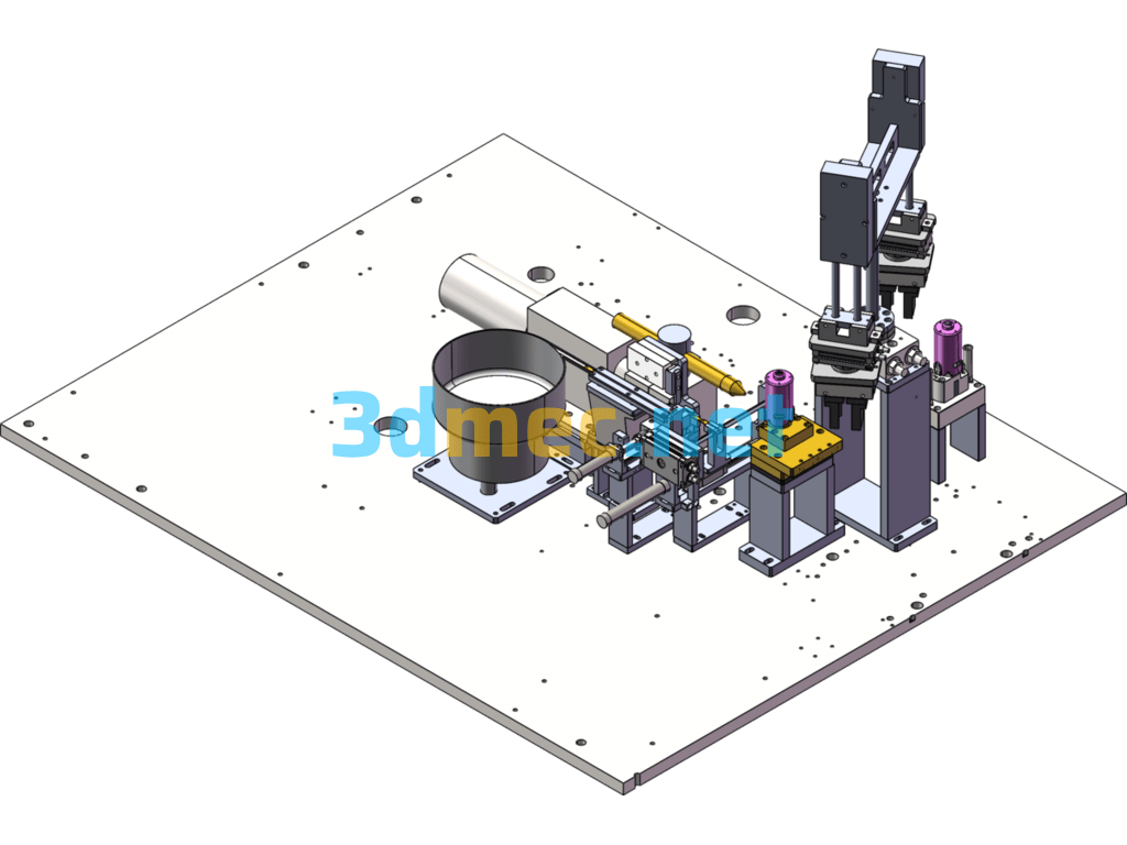
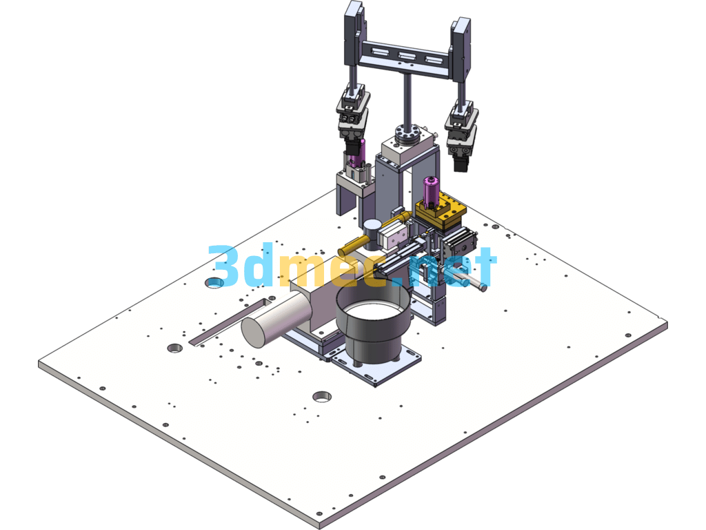
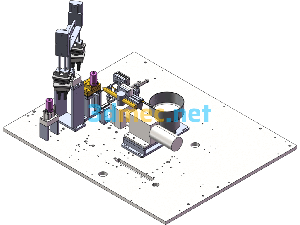
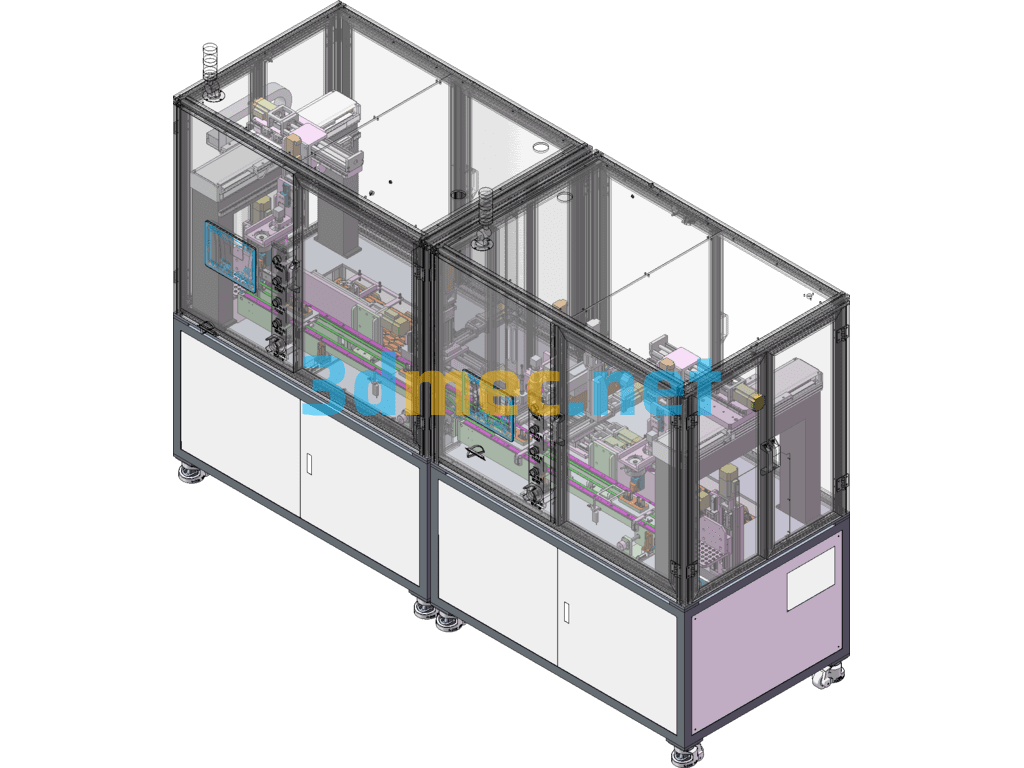
The drawing of the machine housing vibration plate material separation, feeding, welding and unloading mechanism equipment is for welding small hardware pieces on the micro motor housing. The main design principle is that after the small parts are sent out through the vibration plate, the direct vibration material continues to feed the materials and performs a material separation at the rear end of the direct vibration. Since the product needs to stand up when it is discharged, and it can only be discharged flatly during the direct vibration, a rotating structure is added at the back to enable the product to stand up, so that the cylinder can push the product to the position where it needs to be welded for welding. After the small parts are welded to the machine housing, there is a clamping robot structure to clamp the product down. In this way, the overall workflow is completed. The design idea of the mechanical structure is very good. I hope that friends who are doing similar assembly and non-standard automation can download it to help. 3D model of the direct vibration material separation, welding and unloading structure diagram, SolidWorks 2013 source file has editable parameters.
Specification: Casing Vibration Plate Material Feeding Welding And Unloading Mechanism – 3D Model SolidWorks
|
User Reviews
Be the first to review “Casing Vibration Plate Material Feeding Welding And Unloading Mechanism – 3D Model SolidWorks”
You must be logged in to post a review.




There are no reviews yet.