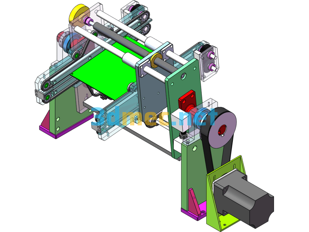
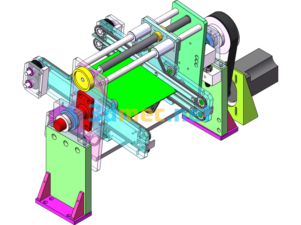
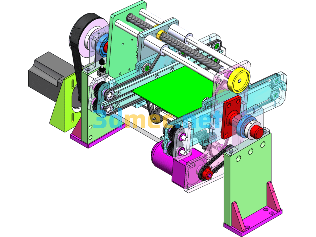
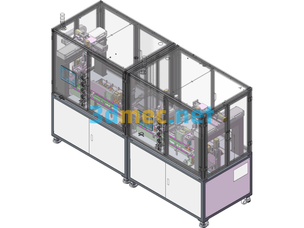
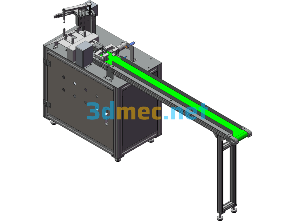
Flipping mechanism drawing PCB board flipping machine is a set of flipping mechanism drawings, which is used to convey products and perform flipping operations. Now many products such as PCB boards also need some glue or soldering on the back after the front processing is completed. This structure is divided into flipping conveying and width adjustment functions. Different specifications of carriers can be adjusted to adapt to products of different sizes through the width of the track. The synchronous wheel of the PCB board flipping machine also adopts a 1:5 ratio to ensure the strength and stability of the flipping. This flipping structure has been mass-produced and is very stable. Friends who are interested are welcome to download and learn
Specification: PCB Board Flipping Machine, Flipping Mechanism Drawings – 3D Model SolidWorks
|
User Reviews
Be the first to review “PCB Board Flipping Machine, Flipping Mechanism Drawings – 3D Model SolidWorks”
You must be logged in to post a review.



There are no reviews yet.