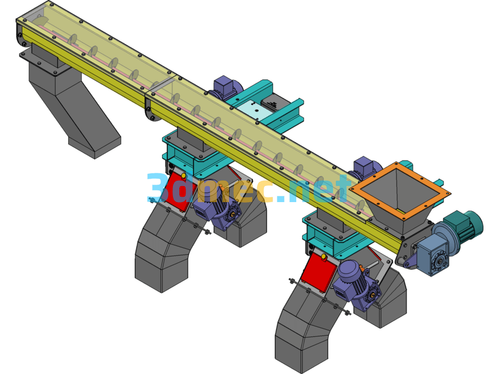
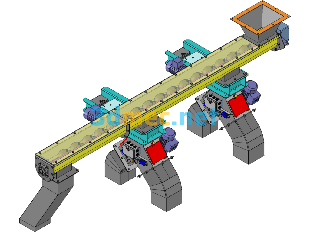
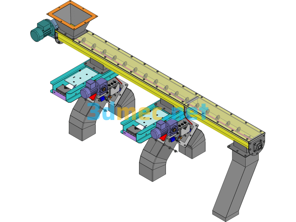
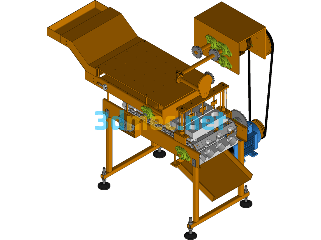
Screw conveyors are divided into two types in terms of conveying form: shaft screw conveyors and shaftless screw conveyors, and in terms of appearance, they are divided into U-shaped screw conveyors and tubular screw conveyors. Shaft screw conveyors are suitable for non-sticky dry powder materials and small particle materials (for example: cement, fly ash, lime, grain, etc.), while shaftless screw conveyors are suitable for conveying sticky and easily entangled materials. (For example: sludge, biomass, garbage, etc.) The working principle of the screw conveyor is that the rotating spiral blades push the materials to be conveyed by the screw conveyor. The force that prevents the materials from rotating with the screw conveyor blades is the weight of the materials themselves and the friction resistance of the screw conveyor casing to the materials. The spiral blades welded on the rotating shaft of the screw conveyor have different surface shapes, such as solid surface, belt surface, and blade surface according to the different conveying materials. The screw shaft of the screw conveyor has a thrust bearing at the end of the material movement direction to give the screw an axial reaction force with the material. When the machine is long, an intermediate hanging bearing should be added.
Specification: Screw Conveyor 3D Model – 3D Model SolidWorks
|
User Reviews
Be the first to review “Screw Conveyor 3D Model – 3D Model SolidWorks”
You must be logged in to post a review.




There are no reviews yet.