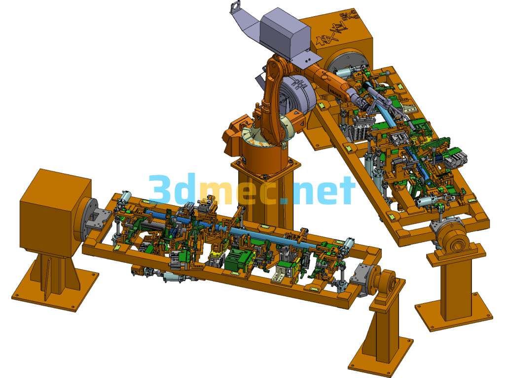
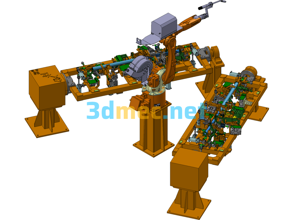
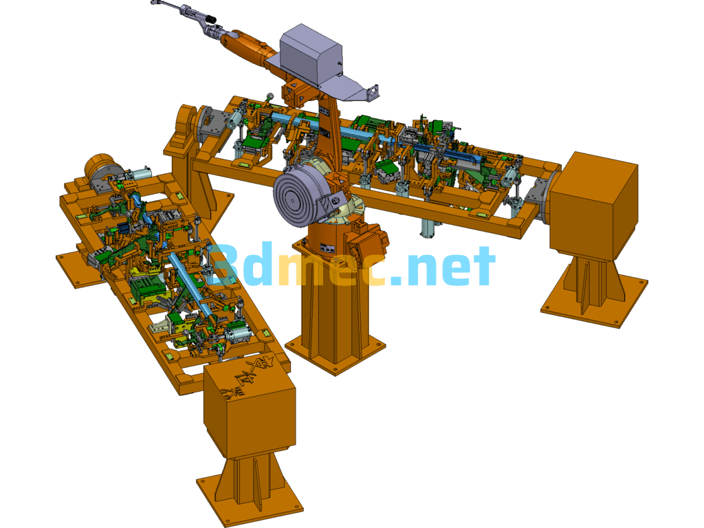
The instrument beam assembly is welded from 18 small stamping parts, and is required to meet the production program of 60,000 vehicles per year. The instrument beam has a large number of stamping parts and a wide variety of plate thicknesses, so the welding assembly is difficult. According to process analysis, CO2 gas shielded gas welding is suitable for welding, with a weld length of 1420mm and 45 welds. Since the weld positions are three-dimensionally cross-distributed and each bracket position has assembly accuracy requirements, the automation requirements for this station are relatively high. Manual welding is far from meeting the requirements in terms of welding quality, production cycle, product stability, etc. Therefore, the final process plan determines that the assembly is welded by CO2 gas shielded welding on all welding points through the welding robot workstation
Determine the height of the robot and the distance from the front, back, left and right to ensure that all welding points are covered within the working range that the robot welding gun can reach. The most reliable method for optimizing the design is to simulate the actual welding work through the robot simulation software. The method is to add the 3D model of the station fixture, workpiece and welding gun, assemble and debug the workstation in the virtual environment, and find out whether there is interference, so as to adjust the relative size of each part to achieve the best.
Each station can be reciprocated around the horizontal axis of the positioner. During welding, its posture can coordinate with the robot to meet the requirements of the welding process. It is mainly composed of 2 external axis servo motors (i.e. positioners) and their reducers, coordination software, converters, cables, 2 sets of fixture flipping mechanisms, servo drive systems, etc. The 2 sets of flipping mechanisms are driven by the positioner, and the system is realized by the robot control system.
The driven shaft is connected to the connecting plate and installed on the mounting seat. The welding fixture flipping mechanism is connected to the connecting plate, and considering the processing error and installation convenience of the welding fixture, the positioner and the driven shaft are height-adjustable, and the driven shaft is a universal rotating bearing, so as to avoid machining errors and facilitate installation and maintenance.
Gun cleaning and silicone oil spraying device: a total of 1 set, consisting of a gun cleaning mechanism, a clamping mechanism and a silicone oil spraying mechanism. The actions are as follows:
The robot moves the welding gun to the gun cleaning device – the gun cleaning device clamps the welding gun – the automatic gun cleaning – the robot moves the welding gun to the silicone oil spraying location – the silicone oil is sprayed – the robot moves the welding gun back to its original position.
This set of welding clamps is a frame structure, which is convenient for the robot welding gun to approach the workpiece. There are 25 active positioning pins, 2 fixed positioning pin sleeves, and 3 fixed pins, which are convenient for the workpiece to be taken out of the fixture. The second station is the same as the first station to increase production capacity and avoid robot waiting time, so that the robot does not stop working when manually loading and removing parts, thereby improving work efficiency.
Specification: Robotic Arc Welding Fixture For Automobile Instrument Beam Frame – 3D Model SolidWorks ProE Creo.Elements Catia
|
User Reviews
Be the first to review “Robotic Arc Welding Fixture For Automobile Instrument Beam Frame – 3D Model SolidWorks ProE Creo.Elements Catia”
You must be logged in to post a review.




There are no reviews yet.