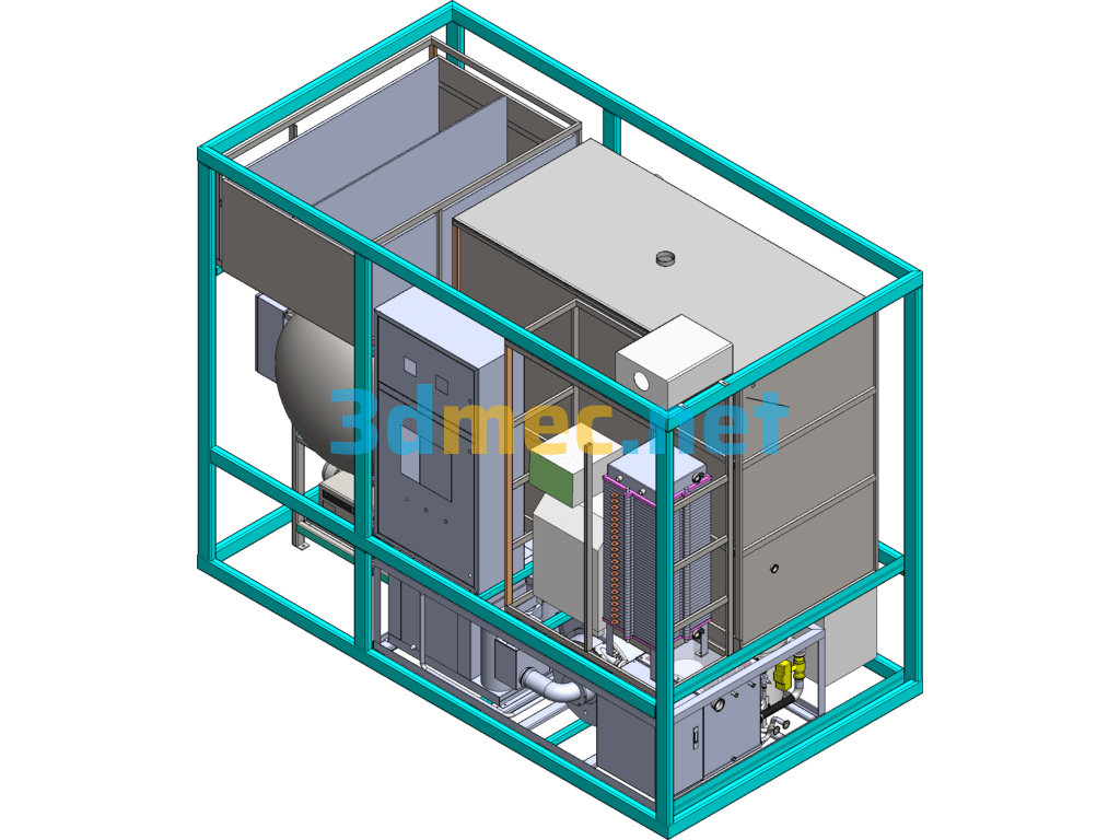
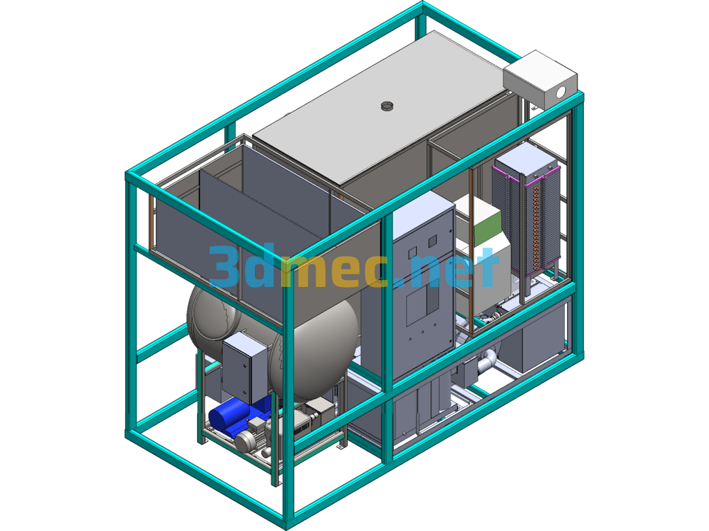
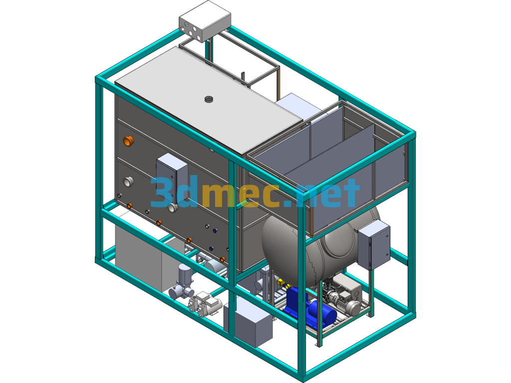
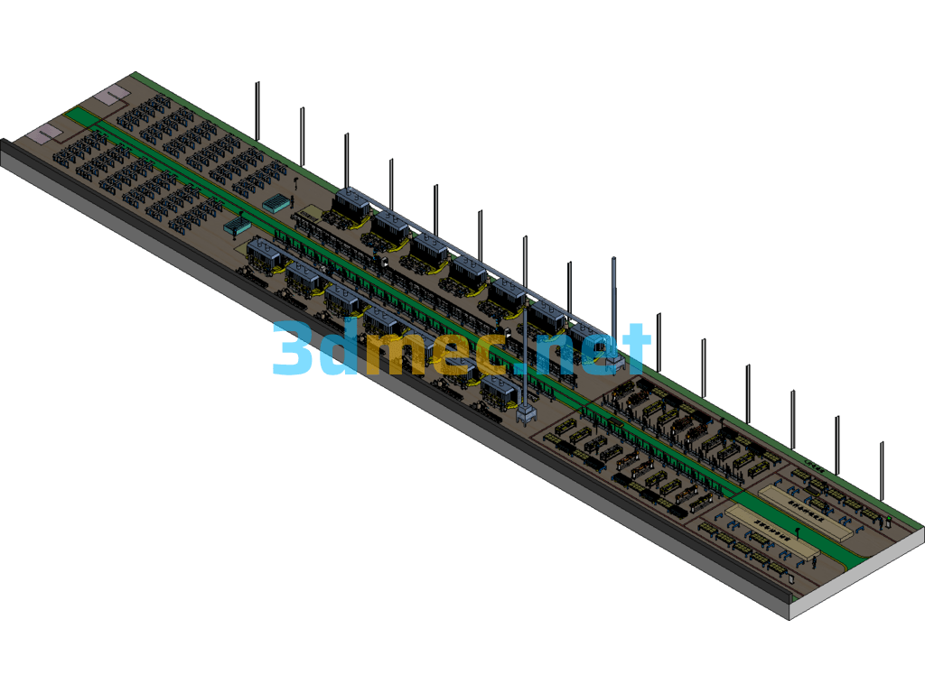
The 3D model of the sewage treatment assembly layout diagram includes: 001. System frame assembly, 002. Vacuum collection system, 003. Sedimentation electrolysis system, 004. Slag scraping and sedimentation MBR membrane system, 005. Super gravity drying system, 006. Electrical control system, 007. Commonly used pipeline accessories, 008. Accessory equipment, 009. Purchased standard parts, etc. The file is in SolidWorks format, with editable parameters, and has a certain reference value. Welcome to download.
Specification: Sewage Treatment Assembly Layout Diagram – 3D Model SolidWorks
|
User Reviews
Be the first to review “Sewage Treatment Assembly Layout Diagram – 3D Model SolidWorks”
You must be logged in to post a review.




There are no reviews yet.