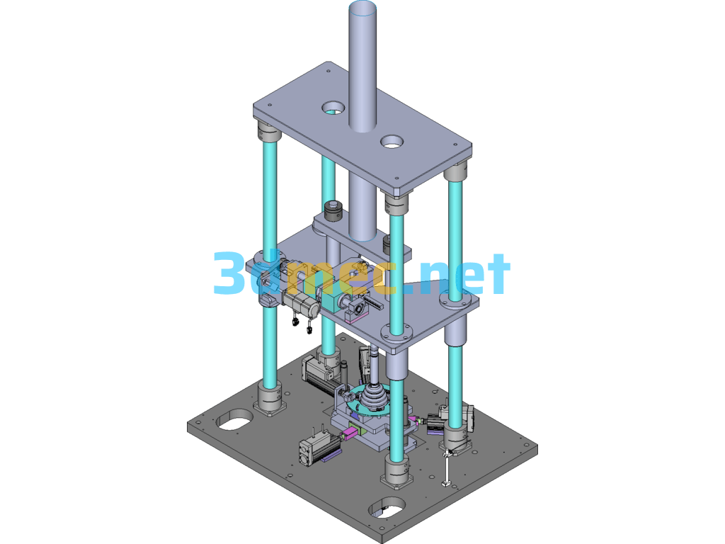
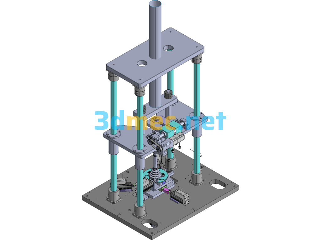
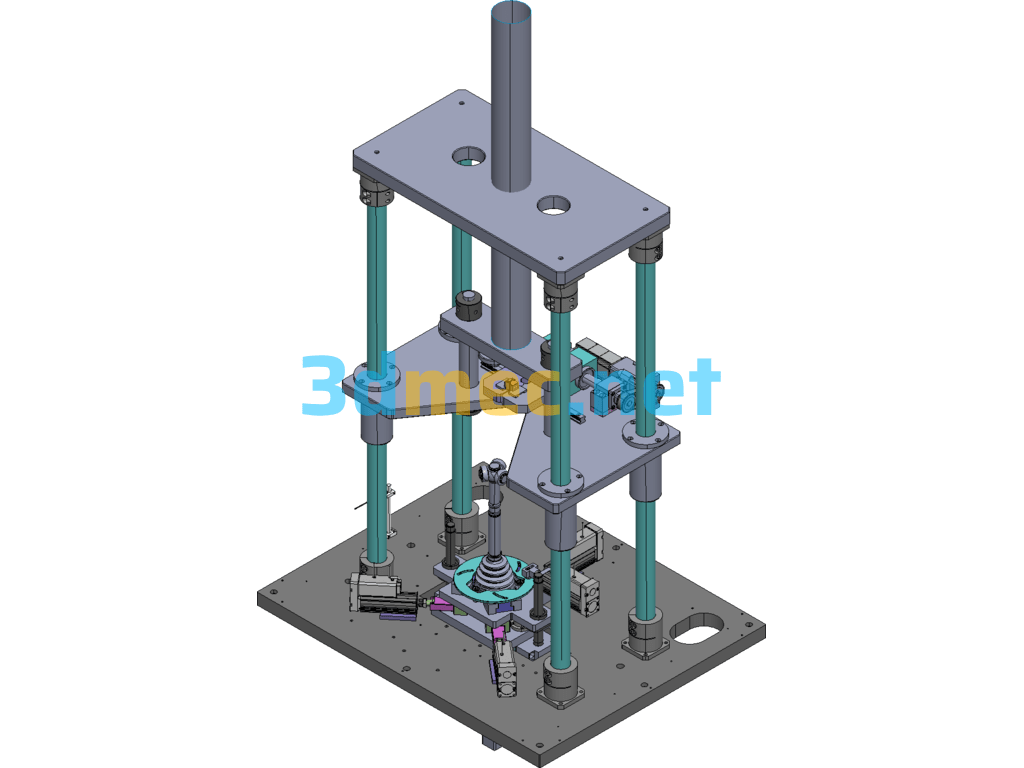
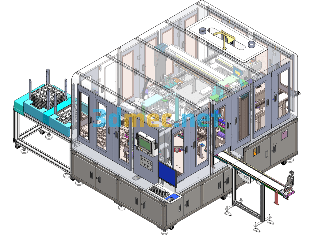
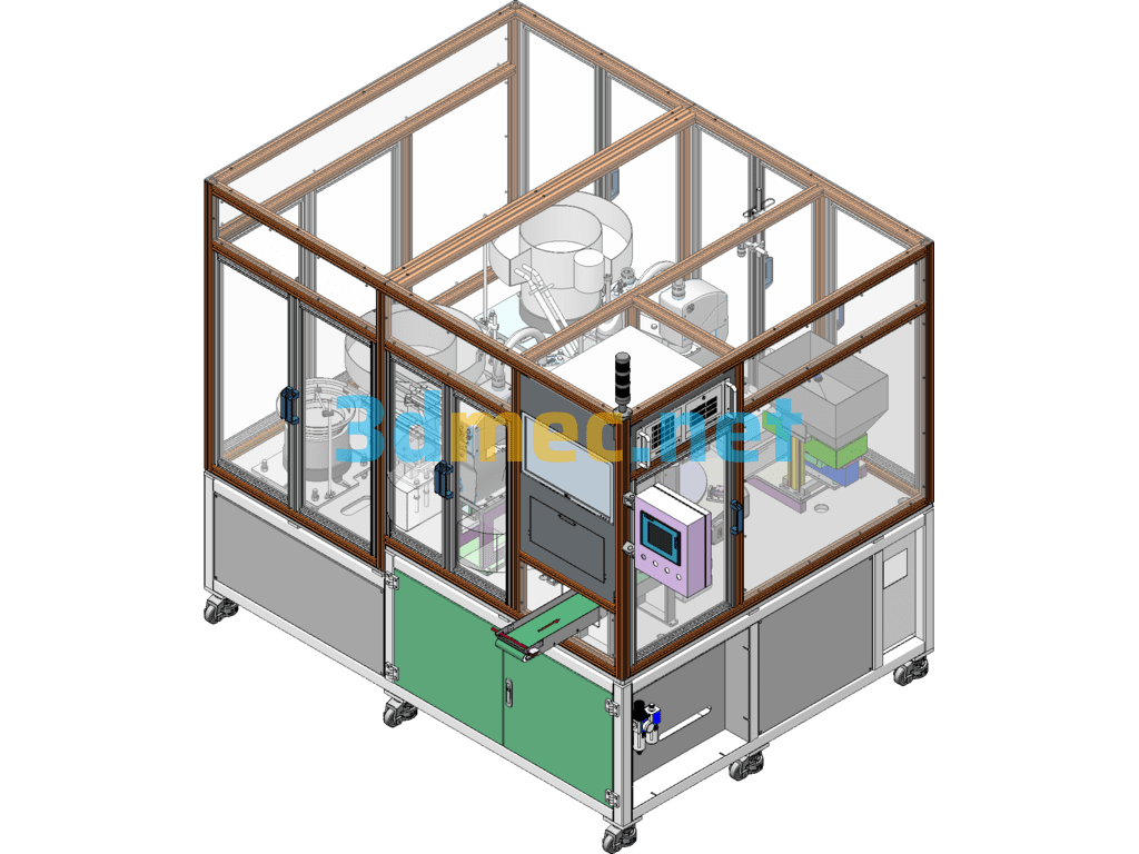
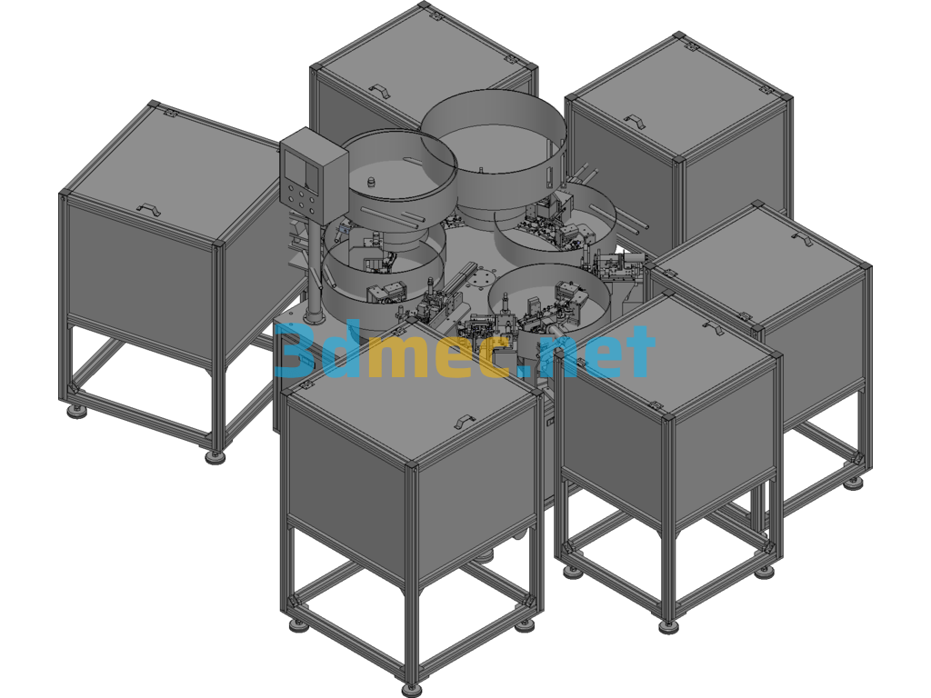
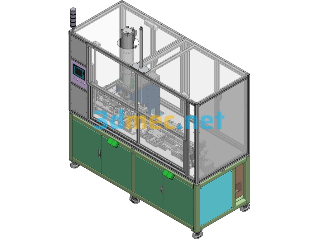
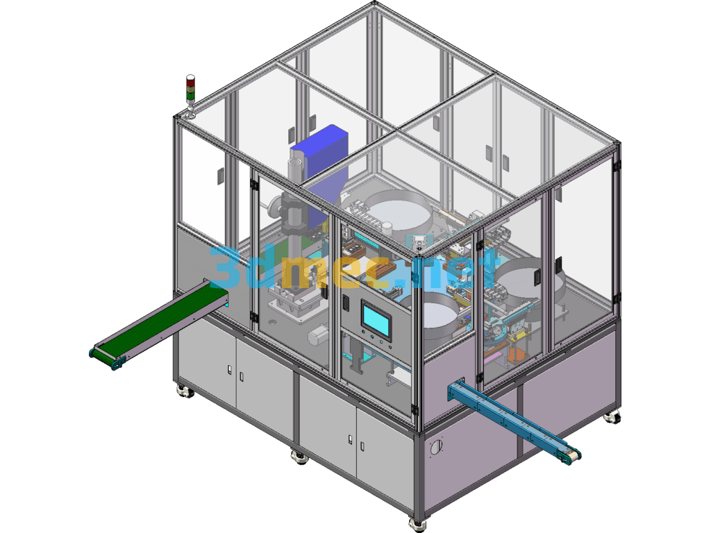
Automobile steering fixed joint press-in assembly machine Automobile steering fixed joint, loading clamping press-in, with pressure sensor sensing pressure and position sensor to ensure pressing in place.
1. The clamping servo screw drives the clamping jaw to move the corresponding distance according to the outer diameter of the core shaft (the general outer diameter size is 17-35mm);
2. The servo press moves the corresponding distance according to the height of the core shaft
(General height size is 200-900mm);
3. Manually put the core shaft on the equipment, and pre-position the back-pull chuck;
4. Start the equipment to clamp the servo screw and carry the chuck to clamp and position the core shaft, and at the same time the back-pull chuck contacts the back-pull force point;
Specification: Automobile Steering Fixed Joint Press-In Assembly Device (PPT Detailed Explanation) – 3D Model SolidWorks
|
User Reviews
Be the first to review “Automobile Steering Fixed Joint Press-In Assembly Device (PPT Detailed Explanation) – 3D Model SolidWorks”
You must be logged in to post a review.




There are no reviews yet.