3D Digital Model + BOM + Design Manual Of Automobile Glass Delay Rack Equipment – 3D Model SolidWorks
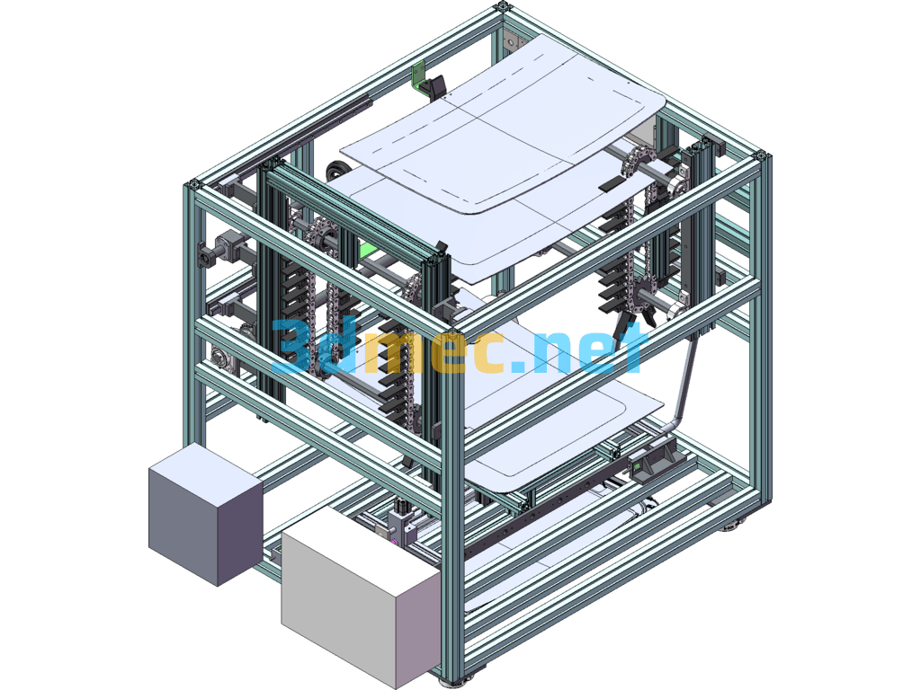
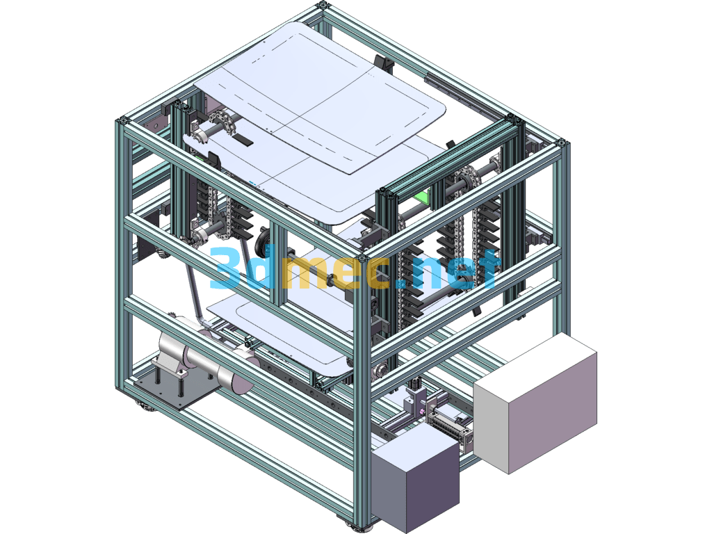
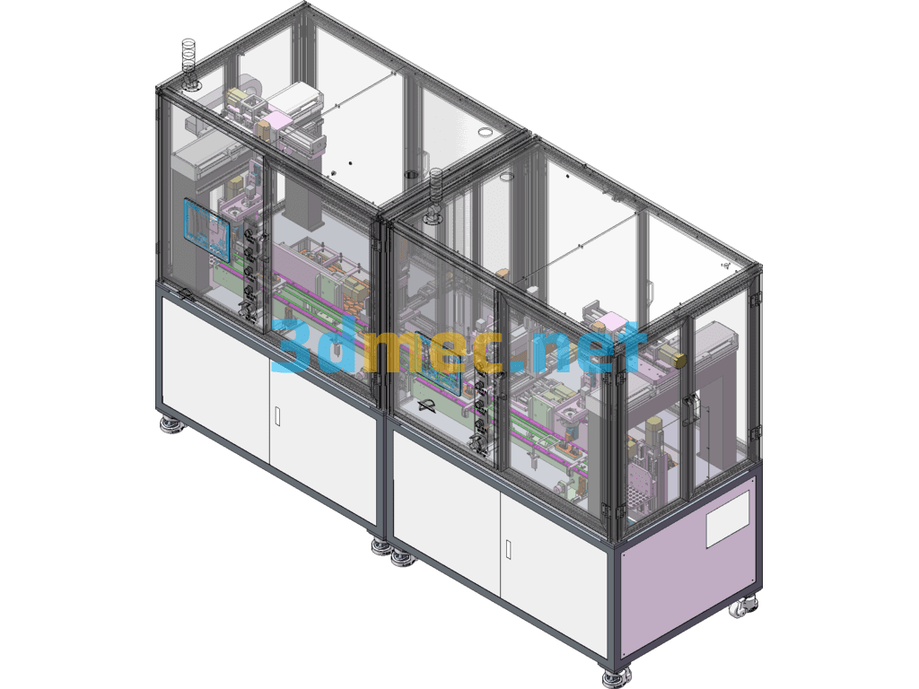
Function: Carrying the primed glass, one-way transmission within the set time, convenient for glass placement and removal operations, with exhaust/exhaust interface
Error prevention function: The minimum drying time is limited to 20min, first in first out
Number of operators: 1 person
Continuous use time: 24H/day
Total cycle time: < 25 sec
Manual operation time: < 25 sec
Product switching tool adjustment time: < 1 min (loading width adjustment, glass support position adjustment)
Noise level: less than 70dB from the noise source to 1m away
Technical description of structural components
• The rack adopts 50*50 Bosch aluminum profile, with overall dimensions: W1500 × D1100 × H1500mm (maximum glass 800 ×1000). • Plexiglas cover plates are installed on the back, left and right sides and front of the workbench; • The effective number of layers for drying glass is 12, with a layer spacing of 35~50mm, and the chain load requirement cannot be less than 80KG (calculated according to the weight of the glass). • The glass support uses black nylon (flat surface) and is covered with black felt to avoid scratching the glass. The support length is 65mm. • Conveying tray: The tray frame is I-shaped (350X450), and a cylinder (adjustable running speed) is installed on the lower side, which is used to transport the glass forward and backward. Four suction cups (FESTO brand, Φ80) are installed on the tray, and the position can be adjusted manually. When the button is pressed manually, the conveyor frame extends out with a piece of original glass. After the glass is extended, the lifting device starts to lift the glass (the height is not less than 600), and then tilt it inward (about 30 degrees). After the glass is taken away, the lifting device automatically falls and retracts, and then the chain drops one grid; • The left side of the chain is fixed, and the right side is adjustable, with an adjustment range of 300mm; • The control display screen is installed in the upper left corner of the front side (the top is installed on the profile), and a plexiglass protective cover is installed outside the screen. • Transmission mechanism. It consists of a frequency converter + transmission motor + reducer. • The cables between the electric cabinet and the outside world are connected by quick connectors. The control cabinet is placed at the bottom of the lower left and can be pushed and pulled out for easy maintenance. • The transmission mechanism requires chain tension adjustment (to prevent loosening during transmission) and is adjustable in the axial direction. The adjustable range is 0-30MM.
• PLC control system: Production starts: The glass with primer coating is put into the top layer of the delay rack from the top. The top layer sensor senses the glass. Press the "down one grid" button, and the chain goes down one grid. Then put the glass in, and the chain goes down automatically. Take out the glass: When the glass falls on the tray and reaches the set time, press the "in/out" button, and the tray will extend the bottom layer of glass. During the extension process, the barcode scanner will scan the barcode information. If it is not read, the red light will be on and the alarm will be turned on. The reset button can be used to reset until the barcode is scanned. The operator can take the glass from the tray (the ejector automatically falls and retracts). • The glass removal button ① is installed on the top of the left and right sides (2), the button box is flush with the side of the profile, and the button is extended. • When the glass is taken away before the time is up, an alarm must be issued; • Buttons on the control panel (from left to right): mode knob ②, control button ③, down one grid ④, reset ⑤, emergency stop button ⑥, model see the table below. • Install a three-color light on the right profile (close to the rear 1500 high profile). • The electrical control cabinet is placed on the lower left rear side, the cabinet size is 400X600). • Limits are required at the rear and sides (the material is black nylon sheet, 2 at the rear and 1 at the side), and safety protection is provided in front of the glass;
Specification: 3D Digital Model + BOM + Design Manual Of Automobile Glass Delay Rack Equipment – 3D Model SolidWorks
|
User Reviews
Be the first to review “3D Digital Model + BOM + Design Manual Of Automobile Glass Delay Rack Equipment – 3D Model SolidWorks”
You must be logged in to post a review.



There are no reviews yet.